
Removable pipe insulation system

Active Publication Date: 2020-04-28
BOND BRETT +1
View PDF6 Cites 0 Cited by
  • Summary
  • Abstract
  • Description
  • Claims
  • Application Information

AI Technical Summary

Benefits of technology

This patent is about a system for insulating pipes, which consists of layers of waterproof material, an insulation layer, and a cover. The cover can have an inside and outside skin, and there are holes in the first layer that allow air to pass through. The system also has adhesive between the first layer and the insulation layer, and the two layers form a sleeve that can be secured to the pipe. The cover can have elastic edges and the two layers can be folded over and secured with tape. The technical effect of this system is that it provides effective insulation for pipes while also allowing air to pass through and the cover to be securely attached to the pipe.

Problems solved by technology

Insulation, particularly outdoor insulation, is vulnerable to moisture, which may result in a deterioration of insulative value.
When the insulation is placed on pipes, moisture in the insulation may also lead to corrosion of the pipes.
When wet, chemicals in the insulation react with virtually all metal pipes, causing corrosion under insulation (CUI).
Furthermore, traditional insulation is not easily reused.
Inspection and service typically renders the existing insulation useless, requiring expensive replacement.
The seams are caulked in an attempt to prevent moisture from reaching the insulation, but this attempt is typically unsuccessful.
These modular systems do not, however, address the moisture problem.
The insulation in such modular systems is still vulnerable to moisture, and the non-insulative elements of such systems inadequately protect the insulation from moisture or the underlying pipes from corrosion.
Attempts have been made to seal insulation inside a waterproof casing, but such attempts have produced new challenges.
Specifically, given the compressible nature of traditional insulation, air is typically trapped within the waterproof casing along with the insulation.
As the insulation is wrapped around a pipe, the air forms a bubble that often makes proper wrapping difficult if not impossible and increases the possibility of rupture of the waterproof casing, allowing moisture to reach the insulation and defeating the purpose of the casing.

Method used


Image

  • Removable pipe insulation system
  • Removable pipe insulation system
  • Removable pipe insulation system

Examples


Embodiment Construction

[0026]The devices and methods discussed herein are merely illustrative of specific manners in which to make and use this invention and are not to be interpreted as limiting in scope.

[0027]While the devices and methods have been described with a certain degree of particularity, it is to be noted that many modifications may be made in the details of the construction and the arrangement of the devices and components without departing from the spirit and scope of this disclosure. It is understood that the devices and methods are not limited to the embodiments set forth herein for purposes of exemplification.

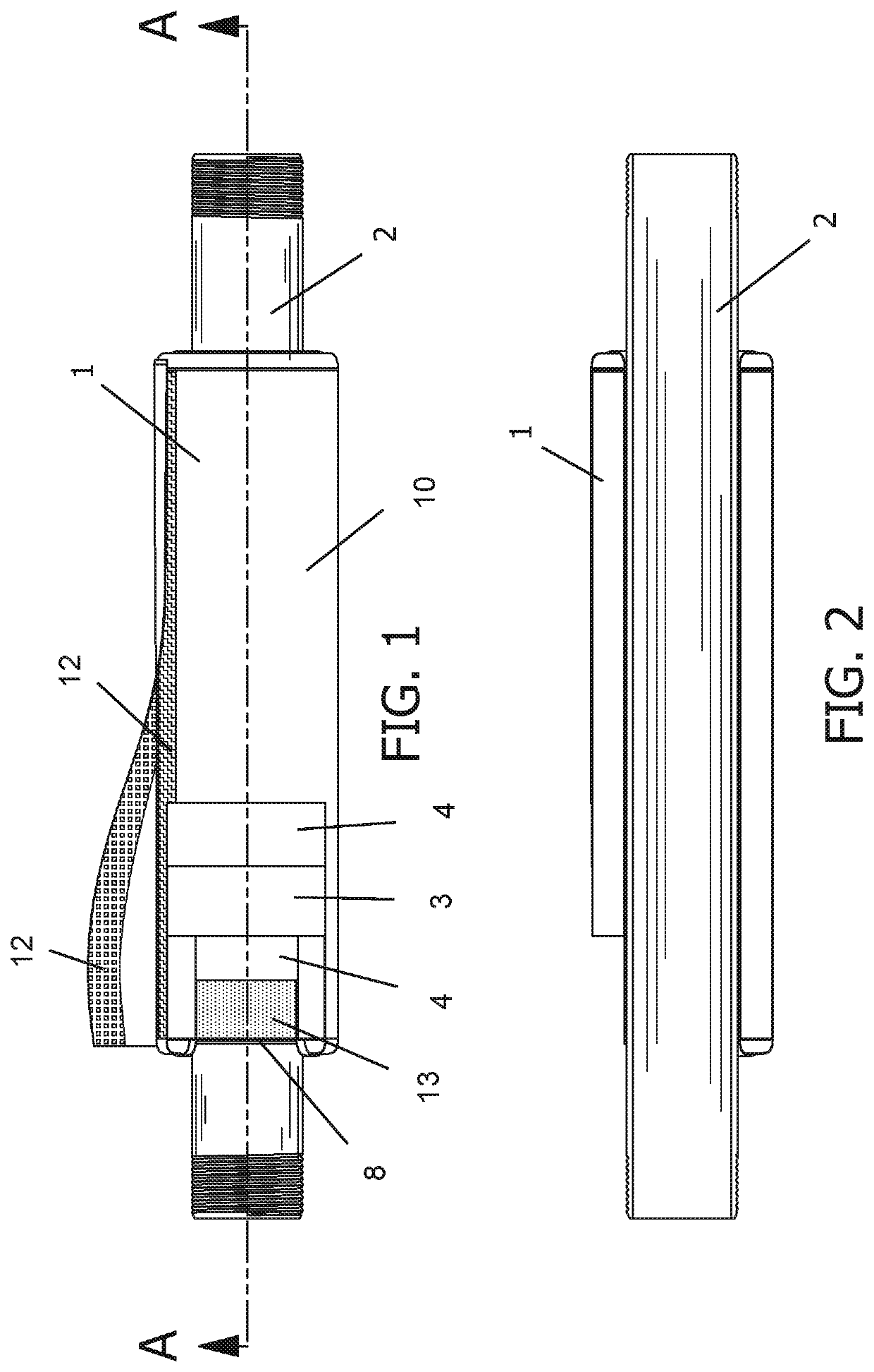
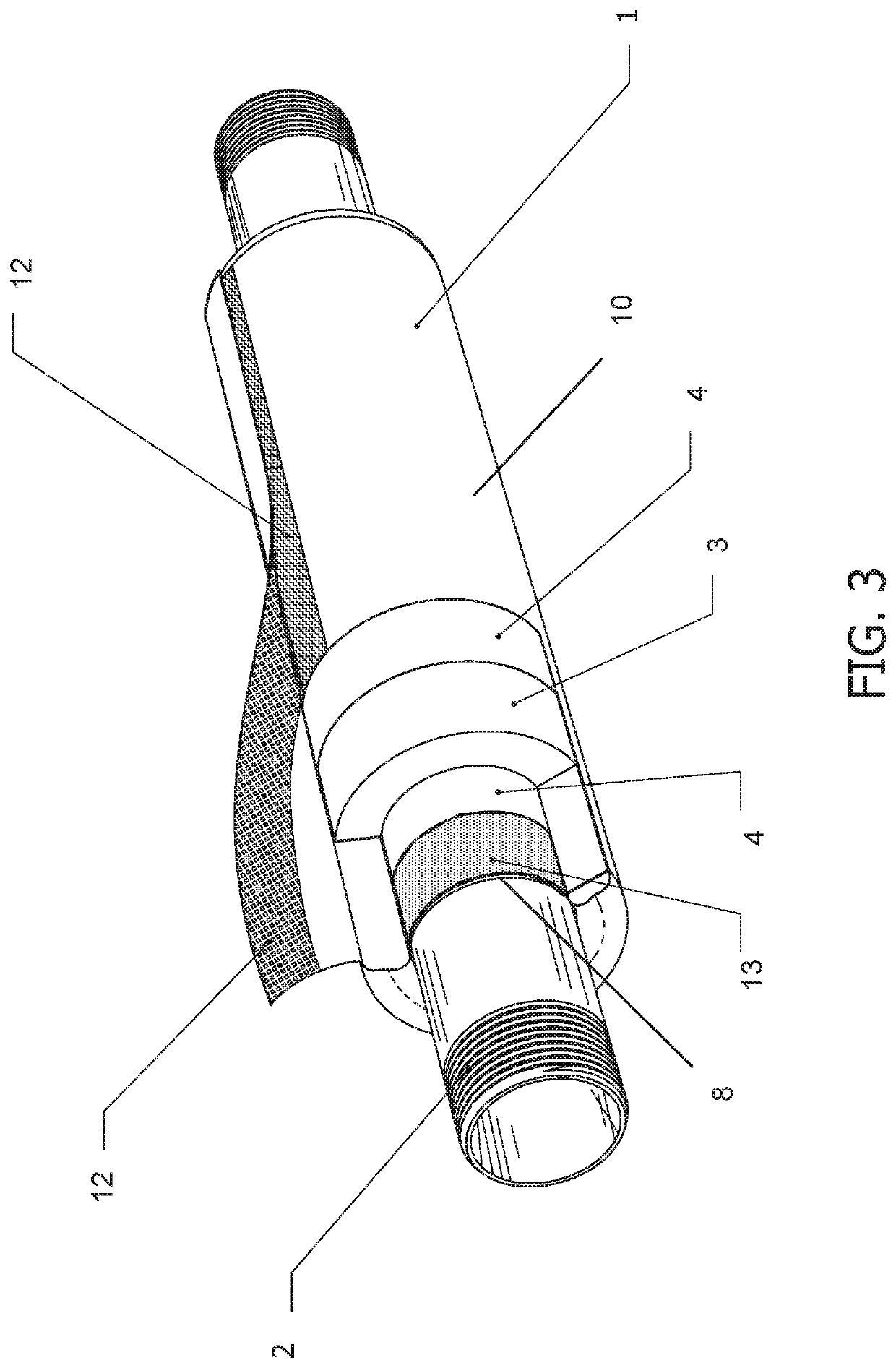
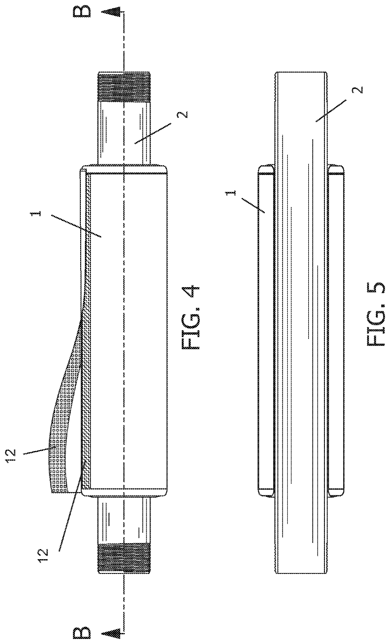
[0028]In general, in a first aspect, the invention relates to a removable pipe insulation system. The system may be modular: it may include a plurality of components 1, each tailored for a standard pipe element 2. Such elements may include straights, tees, elbows, flanges, valves, nipples, or other elements in any desired size. Each component 1 of the system may be shaped and sized a...


PUM


Abstract

A removable pipe insulation system comprising one or more components, each component comprising insulation in a waterproof covering with at least one opening for air to exit the covering during use. The insulation in the covering may be surrounded by an inside skin with a plurality of holes formed through hot micro perforation. The inside skin may be surrounded by an outside cover, which may be edged in elastic binding and which may attach to itself by hook and loop fastener. The component may be wrapped around a pipe element and secured to provide insulation to the pipe element while protecting the insulation from moisture and protecting the pipe element from corrosion under insulation.

Description

CROSS REFERENCE[0001]This application is based on and claims priority to U.S. Application No. 62 / 423,969 filed Nov. 18, 2016.BACKGROUND OF THE INVENTIONField of the Invention[0002]This invention relates generally to pipe insulation and more particularly, but not by way of limitation, to a system of removable waterproof insulation for pipes.Description of the Related Art[0003]Insulation, particularly outdoor insulation, is vulnerable to moisture, which may result in a deterioration of insulative value. Traditional insulation wicks moisture, exacerbating any moisture exposure. When the insulation is placed on pipes, moisture in the insulation may also lead to corrosion of the pipes. When wet, chemicals in the insulation react with virtually all metal pipes, causing corrosion under insulation (CUI). Furthermore, traditional insulation is not easily reused. Inspection and service typically renders the existing insulation useless, requiring expensive replacement.[0004]Typically, insulati...

Claims


Application Information

Patent Timeline
IPC IPC(8): F16L59/00F16L59/02F16L58/16F16L59/07
CPCF16L59/022F16L59/029F16L58/16F16L59/07F16L59/026F16L59/163
Inventor BOND, BRETTMILLIGAN, ALAN
Owner BOND BRETT
Learn More