Methods and systems for plasma deposition and treatment

a plasma and treatment technology, applied in the field of methods and systems for plasma deposition and treatment, can solve the problems of the deployment of manufacturing equipment, the effect of vacuum or reduced pressure environment, and the cost of performing such a deposition

Active Publication Date: 2018-12-27
VANDERMEULEN PETER F
View PDF4 Cites 6 Cited by
  • Summary
  • Abstract
  • Description
  • Claims
  • Application Information

AI Technical Summary

Benefits of technology

[0022]In accordance with one or more embodiments, methods and systems are provided wherein a waveguide receives microwave radiation from a source and wherein the waveguide has slots cut into one or more of its side to allow the microwave radiation to enter an ECR plasma chamber and wherein there are pipes or tubes on the opposite side of the microwave slots to allow for the introduction of materials such as gasses, powders, liquids, solids or any combination of these and wherein the plasma chamber is outfitted by a set up magnets to create an ECR effect. In some embodiments, the waveguide and plasma chamber are shaped in a bend to conform to the surface of the object to be coated such as a cylinder or such as a pipe. The waveguides and / or plasma chambers can be constructed to assume many different shapes and configurations so as to effectively coat a non-planar surface. In some embodiments, the waveguide is circular in shape. In yet another embodiment, the waveguide is helical in shape. In a further embodiment, the waveguide is shaped to direct microwaves to a part of a human anatomy, wherein one advantage is that the microwave guide may provide a focal point inside the human body where as a result, the concentration of microwaves is much higher than at any point on the surface of the body. In another embodiment, the microwave guide is shaped to concentrate microwave radiation in a single point or along a single line so that the local microwave power is substantially higher than the power emitted from the individual slots.

Problems solved by technology

Oftentimes a balance has to be struck between technical concerns such as layer adhesion, contamination from undesirable elements, deposition rates, and uniformity (both on a global and on a microscopic scale), and commercial concerns such as the cost of performing such a deposition (materials costs and the effective use of the materials) as well as the cost of the manufacturing equipment deployed.
Generally, processes that employ a vacuum or reduced pressure environment are subject to higher capital equipment costs and demonstrate lower deposition rates.
Furthermore, some processes may not work at all at higher pressures and therefore require a lower pressure or vacuum level operating regime.
A common problem with arc discharge plasmas is that they consume their electrodes over time.
In several processes such as in the deposition of materials that are required to remain very pure, such co-deposition can be detrimental, even at very low contamination levels.
As an example, even small amounts of co-deposited metals can be detrimental to the functioning of semiconductors and solar photovoltaic materials.
Most ECR plasma systems require vacuum levels well below atmosphere to be able to operate, and thus require expensive equipment.
Common problems with the application of these plasmas to materials and substrates involve the co-deposition of undesirable materials that are introduced through either the erosion of the chamber that contains the plasma, or by the use of starting materials that already contain such contamination.
One disadvantage of shielding and liners is that they too eventually get coated with the to-be-deposited materials or with other residual process effluents.
Such depositions ultimately may result in the materials flaking off and falling on the substrate that is in process.
These unintended particles or flakes are generally very destructive to the semiconductor devices in process, and great care is typically taking to minimize any risk of particles falling on the substrate.
Low deposition rates can mean long process times, which means low equipment throughput.
The cost of vacuum equipment is typically very high and the combination of long deposition times and high equipment cost is usually not desirable.
However, vacuum based processes typically exhibit good adhesion to the substrate because of the absence or lowering of surface contamination (water molecules are a primary culprit in poor adhesion).

Method used


Image

  • Methods and systems for plasma deposition and treatment
  • Methods and systems for plasma deposition and treatment
  • Methods and systems for plasma deposition and treatment

Examples


Embodiment Construction

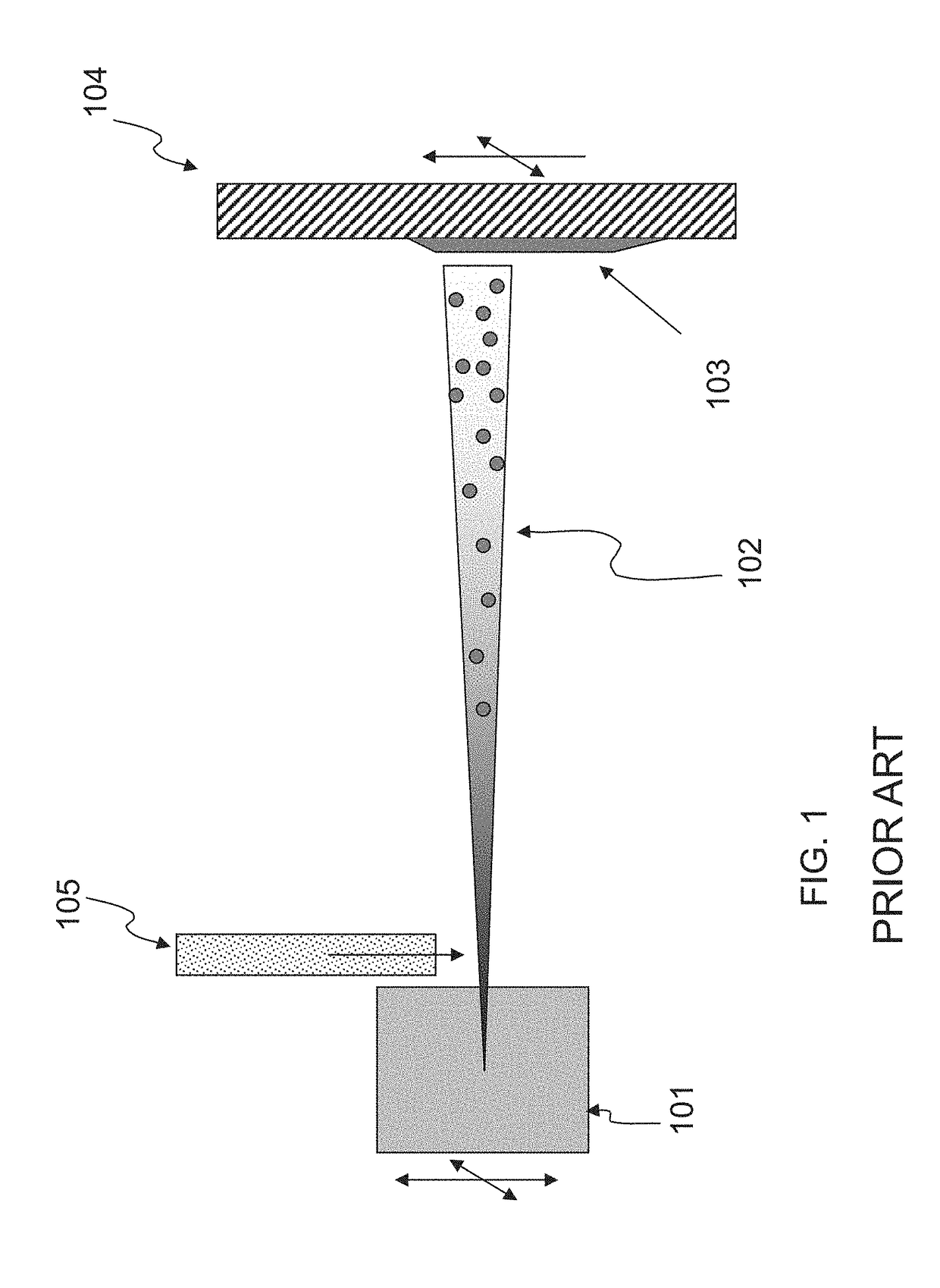
[0084]FIG. 1 is a simplified diagram of components of a Thermal Spray Plasma (TSP) system as is commonly known in the art. A plasma source 101 generates a high temperature plasma environment, typically with temperatures ranging from 5,000 to 12,000° C. The temperature of the plasma is determined by a number of operating parameters, such as the power supplied to the plasma source, the powder or solid material feed rates that are supplied to the source region, the amount of gas that is introduced, the environmental pressure, etc. The introduction of gasses into the plasma chamber results in a plasma jet 102 being emitted from the plasma source. An injector 105 can inject additional materials into the plasma chamber 101 or into a convenient location in the plasma jet 102 that is emitted from the chamber. The materials that are injected into the plasma stream can be in almost any form, whether they are gaseous, liquid, solids, powders and combinations thereof. Common materials that are ...


PUM


Abstract

An ion beam treatment or implantation system includes an ion source emitting a plurality of parallel ion beams having a given spacing. A first lens magnet having a non-uniform magnetic field receives the plurality of ion beams from the ion source and focuses the plurality of ion beams toward a common point. The system may optionally include a second lens magnet having a non-uniform magnetic field receiving the ion beams focused by the first lens magnet and redirecting the ion beams such that they have a parallel arrangement having a closer spacing than said given spacing in a direction toward a target substrate.

Description

CROSS REFERENCE TO RELATED APPLICATION[0001]This application claims priority from U.S. Provisional Patent Application Ser. No. 62 / 525,463 filed on Jun. 27, 2017 and entitled Methods And Systems For Plasma Deposition And Treatment, which is hereby incorporated by reference.BACKGROUND[0002]The present application generally relates to methods and systems for deposition of materials on substrates using plasmas and the treatment of objects using microwave radiation and plasma.[0003]Deposition technologies include physical vapor deposition (PVD), chemical vapor deposition (CVD) (either at atmospheric pressure (APCVD) or reduced pressure (LPCVD)), electroplating, evaporation, thermal flame spray, and thermal plasma spray. Many of these deposition technologies are used for the manufacture of materials layers such as semiconductors, carbon-nanotubes, industrial coatings, biomedical coatings, and the like. Oftentimes a balance has to be struck between technical concerns such as layer adhesion...

Claims


Application Information

Patent Timeline
Patent Type & Authority Applications(United States)
IPC IPC(8): H01J37/14H05H1/46H01J37/147H01J37/05H01J37/317
CPCH01J37/14H05H1/46H01J37/147H01J37/05H01J37/3171H01L31/206H01J2237/14H05H2001/4622H01J2237/152H01J2237/0817H01J2237/057H01L31/1804H01J37/08H01J2237/31701H01J2237/31732H01J37/32192H01J37/32412Y02P70/50H05H1/4622
Inventor VANDERMEULEN, PETER F.
Owner VANDERMEULEN PETER F
Why Eureka
Try Eureka