
Method of manufacturing magnetic material

a manufacturing method and magnetic material technology, applied in the direction of magnetic materials, magnetic bodies, transportation and packaging, etc., can solve the problems of reducing the fesub>2/sub>b phase, reducing the safety control, and shortening the homogenizing heat treatment on the intermediate material, etc., to achieve the effect of decreasing the surface oxide of the iron powder

Active Publication Date: 2018-10-18
NAT INST OF ADVANCED IND SCI & TECH
View PDF0 Cites 1 Cited by
  • Summary
  • Abstract
  • Description
  • Claims
  • Application Information

AI Technical Summary

Benefits of technology

The present invention provides a method for manufacturing a magnetic material that has a high content of a NaZn13-type crystal structure, using a solid phase reaction. The method involves decreasing surface oxides of iron powder, mixing iron powder with a compound powder, and compressing and molding the mixture powder to form a sintered body. The invention can provide a magnetic material with improved properties.

Problems solved by technology

Although the homogenizing heat treatment on the intermediate material may be shortened by these methods, it is still inevitable to pass through the intermediate material.
However, for an alloy manufactured by this method, it is necessary to add approximately greater than or equal to 1.8 at % and less than or equal to 5.4 at % of B in order to obtain a good effect, and there is a problem that a sub-generated phase such as a Fe2B phase may lower properties.
However, as the La oxide is stable, in order to reduce the La oxide, it is necessary to use an alkali earth metal such as Ca, which is extremely active to oxygen, and safety control becomes complicated.
Further, as water washing is essential in order to remove Ca oxide after the reaction, there is a risk that rust is generated at a surface of a generated La(Fe, Si)13-based compound.

Method used


Image

  • Method of manufacturing magnetic material
  • Method of manufacturing magnetic material
  • Method of manufacturing magnetic material

Examples


example 1

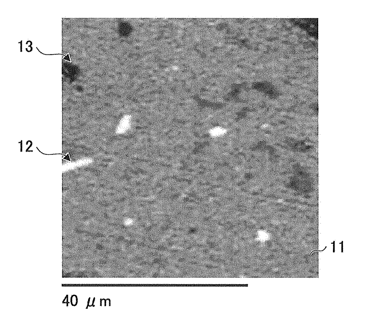
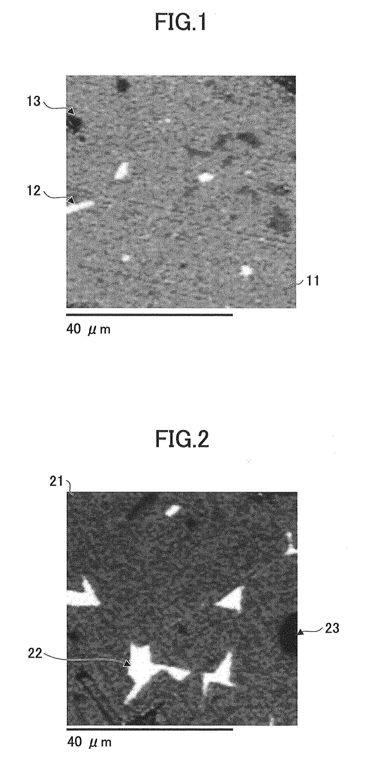
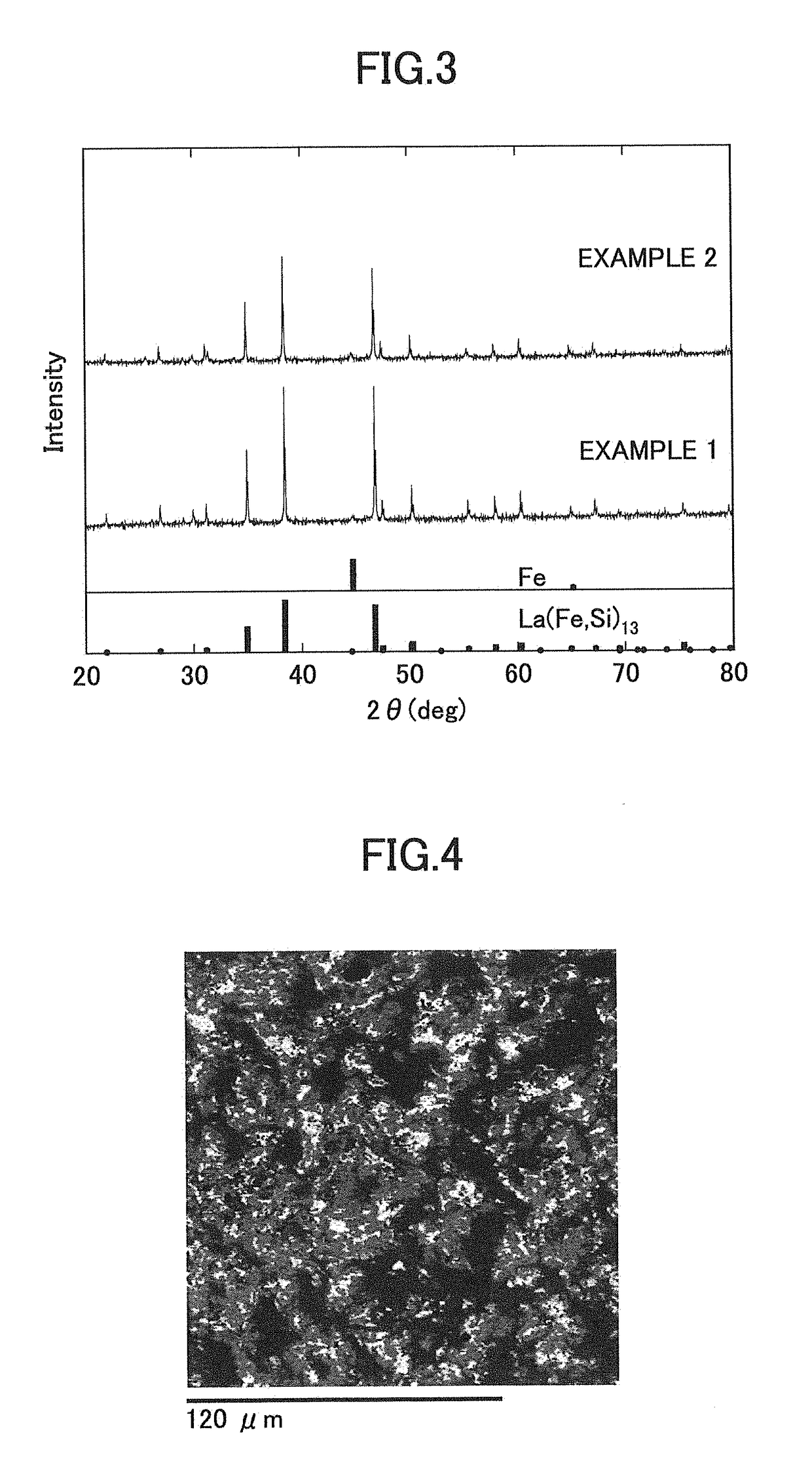
[0108]A magnetic material was prepared and evaluated by the following steps.

(Surface Oxides Decreasing Step)

[0109]100 g of a commercially available iron powder (manufactured by Kojundo Chemical Lab. Co., Ltd, less than or equal to 53 μm of particle size, and purity 3N) was spread on an alumina plate whose diameter was 8 cm, and was placed on a soaking zone of a heating chamber of an electric furnace (iron powder placing step).

[0110]Next, the heating chamber of the electric furnace was evacuated to 1×10⁻¹ Pa by a rotary pump (evacuation step).

[0111]After the degree of vacuum in the heating chamber became 1×10⁻¹ Pa, heating was started and temperature was risen to target temperature of 600° C. by elapsed time of one hour from the start of the heating. After reaching the target temperature, hydrogen was introduced under a condition by which the heating chamber became the same as atmospheric pressure, and the iron powder provided in the heating chamber was exposed to the hydrogen gas fo...

example 2

[0124]A magnetic material was manufactured similarly as example 1 except that the surface oxides decreasing step was performed by the following steps and the obtained iron powder whose surface oxides were already decreased was used, in other words, the magnetic material was manufactured similarly as the powder-molded body forming step and the sintered body forming step of example 1 except the surface oxides decreasing step.

(Surface Oxides Decreasing Step)

[0125]First, 15 g of a commercially available electrolytic iron (manufactured by Showa Denko K.K., product name: Atomiron) was melted and degassed by arc melting in argon, and a button-shaped ingot was formed (iron ingot forming step).

[0126]Next, a drill bit on which industrial diamond was baked was attached to a driller, and the button-shaped ingot formed by the iron ingot forming step was grinded (grinding step).

[0127]The obtained grinded grain was screened by a standard sieve with a reference size defined by JISZ8801 (1982) of 53...


PUM

PropertyMeasurementUnit
temperatureaaaaaaaaaa
pressureaaaaaaaaaa
temperatureaaaaaaaaaa

Abstract

A method of manufacturing a magnetic material, includes a surface oxides decreasing step of decreasing surface oxides of an iron powder; a powder-molded body forming step of mixing the iron powder whose surface oxides are already decreased obtained by the surface oxides decreasing step, and a compound powder “A” constituted by a La element and a Si element, and compressing and molding the obtained mixture powder; and a sintered body forming step of preparing a sintered body from the powder-molded body obtained by the powder-molded body forming step, by a solid phase reaction under vacuum atmosphere.

Description

BACKGROUND OF THE INVENTION1. Field of the Invention[0001]The present invention relates to a method of manufacturing a magnetic material.2. Description of the Related Art[0002]Recently, as a refrigeration technique for decreasing burden on the environment, a magnetic refrigeration method is suggested which is clean and has high energy efficiency, without using a flon (chlorofluorocarbon)-based gas, which induces environmental issues. A magnetic refrigeration material functions as a refrigerant in this magnetic refrigeration method, and in order to operate the magnetic refrigerator at room temperature, a magnetic material is used by which large magnetic entropy variation can be obtained near room temperature.[0003]As a magnetic material that demonstrates preferable characteristics for such magnetic refrigeration, a La(Fe, Si)13-based compound including a NaZn13-type crystal structure is known. The La(Fe, Si)13-based compound is practically advantageous because it can obtain large mag...

Claims


Application Information

Patent Timeline
Patent Type & Authority Applications(United States)
IPC IPC(8): H01F1/01C22C38/02B22F9/04B22F1/00H01F41/02B22F1/12B22F1/145
CPCH01F1/01C22C38/02B22F9/04B22F1/0003H01F41/026H01F41/0266H01F1/015B22F2998/10B22F2999/00C22C38/005C22C2202/02B22F1/145B22F1/12B22F3/02B22F3/1007B22F2201/013C22C38/00
Inventor FUJITA, ASAYAOZAKI, KIMIHIRO
Owner NAT INST OF ADVANCED IND SCI & TECH
Learn More