
Graphene-Reinforced Polymer Matrix Composites

a graphene-reinforced polymer and composite technology, applied in single-layer graphene, chemistry apparatus and processes, transportation and packaging, etc., can solve the problems of insufficient intrinsic strength of a significant number of polymeric materials, slow progress in the development of low-cost methods to effectively produce graphene-reinforced polymer matrix composites, and the inability to meet the requirements of real-world applications. achieve the effect of improving the mechanical properties of bulk polymer

Active Publication Date: 2017-08-03
RUTGERS THE STATE UNIV
View PDF8 Cites 25 Cited by
  • Summary
  • Abstract
  • Description
  • Claims
  • Application Information

AI Technical Summary

Benefits of technology

The patent describes a method for creating a composite of graphene and polymer. This is done by melting the polymer and adding graphite particles, which results in the exfoliation of the graphite and the creation of graphene sheets. The composition can also include other components to improve its properties. The resulting composite has better strength and stiffness, and can be used in various applications such as laminates, molds, and electronics. Additionally, the invention includes a method for making a thermally conductive composite by using a polymer that is inter-molecularly cross-linked. This allows for improved heat transfer and can be used in applications such as electronics.

Problems solved by technology

However, a significant number of polymeric materials fail to be intrinsically strong enough for many of these applications.
Progress remains very slow in the development of low-cost methods to effectively produce graphene-reinforced polymer matrix composites (G-PMCs).
Currently, some of the challenges that exist affecting the development of G-PMCs viable for use in real-world applications include the high cost of the materials and the impracticality of the presently used chemical and / or mechanical manipulations for large-scale commercial production.

Method used


Image

  • Graphene-Reinforced Polymer Matrix Composites
  • Graphene-Reinforced Polymer Matrix Composites
  • Graphene-Reinforced Polymer Matrix Composites

Examples


example 1

on of Graphene-Reinforced Polysulfone (G-PSU)

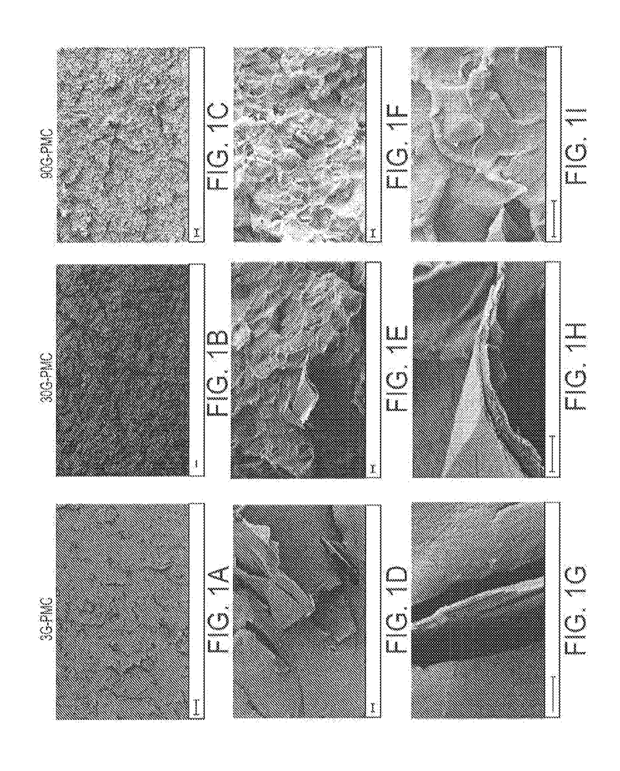
[0102]In one embodiment, a small scale extension mixer with a 10-gram capacity was used to compound 2% of SMG with Udel P-1700 Polysulfone (PSU) at 332° C. (630° F.) and under vacuum for 3, 30, and 90 minutes. The method is described below. Samples collected for characterization after each length of time are referred to as 3G-PMC, 30G-PMC, 90G-PMC.[0103]1. 9.8 grams of PSU were added to the mixer and allowed to become molten.[0104]2. 0.2 grams of SMG were added to the molten PSU and mixed.[0105]3. After 3 minutes of mixing time, 3 grams of the G-PMC were extruded out of the mixer and collected for characterization.[0106]4. 3 grams of 2% SMG in PSU was added to the mixer and mixed.[0107]5. After 30 minutes of mixing time, 3 grams of the G-PMC were extruded out of the mixer and collected for characterization.[0108]6. 3 grams of 2% SMG in PSU was added to the mixer and mixed.[0109]7. After 90 minutes of mixing time, 3 grams of the G-PMC were...

example 2

y Analysis

[0110]A Zeiss Sigma Field Emission Scanning Electron Microscope (FESEM) with Oxford EDS was used to determine the degree of mechanical exfoliation of graphite into multi-layer graphene or graphene nanoparticles and the thickness of these particles. An accelerating voltage of 3 kV and working distance of approximately 8.5 mm was used during viewing. Prior to viewing, specimens from each sample of 3G-PMC, 30G-PMC, and 90G-PMC were notched, cryogenically fractured to produce a flat fracture surface, placed under vacuum for at least 24 hours, gold coated, and stored under vacuum.

Morphology Results

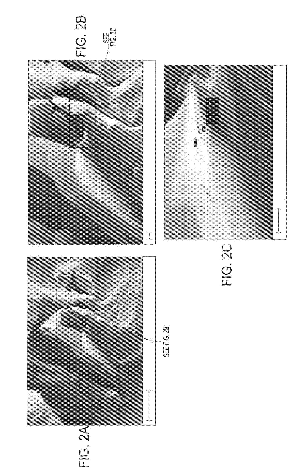
[0111]The morphology of each sample, 3G-PMC, 30G-PMC, and 90G-PMC, at three different scales (magnification) is shown in FIG. 1. In (a-c), a 20 μm scale and 1,000× magnification shows good distribution of multi-layer graphene or graphene within the PSU matrix at each mixing time. In (d-f), a 1 μm scale and 10,000× magnification and (g-i), a 1 μm scale and 50,000× magnification shows m...

example 3

fraction Analysis (XRD)

[0113]XRD analysis on each sample of 3G-PMC, 30G-PMC, and 90G-PMC includes four steps: (1) sample preparation, (2) diffraction pattern acquisition, (3) profile fitting, and (4) out-of-plane (D) crystallite sizes calculation according to the Debye-Scherrer equation.[0114]1. The samples for XRD analysis were prepared by pressing thin films of each sample 3G-PMC, 30G-PMC, and 90G-PMC at 230° C. and 5,500 psi over a 2 minute time period. Each sample was positioned between aluminum sheets prior to pressing using a Carver Uniaxial Press with heated platens.[0115]2. Diffraction patterns of the pressed films were acquired using a Philips XPert powder Diffractometer with sample changer (Xpert) at 40 kV and 45 mA with an incident slit thickness of 0.3 mm from 4°-70° 2θ and a step size of 0.02° 2θ.[0116]3. Diffraction patterns were uploaded into WinPLOTR Powder diffraction graphics tool, without background editing or profile adjustments prior to peak fitting. Single peak...


PUM

PropertyMeasurementUnit
thickaaaaaaaaaa
thickaaaaaaaaaa
thickaaaaaaaaaa

Abstract

A graphene-reinforced polymer matrix composite comprising an essentially uniform distribution in a thermoplastic polymer of about 10% to about 50% of total composite weight of particles selected from graphite microp articles, single-layer graphene nanoparticles, multilayer graphene nanoparticles, and combinations thereof, where at least 50 wt % of the particles consist of single- and / or multi-layer graphene nanoparticles less than 50 nanometers thick along a c-axis direction. The graphene-reinforced polymer matrix is prepared by a method comprising (a) distributing graphite microparticles into a molten thermoplastic polymer phase comprising one or more matrix polymers; and (b) applying a succession of shear strain events to the molten polymer phase so that the matrix polymers exfoliate the graphite successively with each event until at least 50% of the graphite is exfoliated to form a distribution in the molten polymer phase of single- and multi-layer graphene nanoparticles less than 50 nanometers thick along a c-axis direction.

Description

CROSS-REFERENCE TO RELATED APPLICATIONS[0001]This application claims the benefit of priority of U.S. Provisional Application No. 62 / 030,799, filed on Jul. 30, 2014, the entire disclosure of which is incorporated herein by reference.TECHNICAL FIELD[0002]The present invention relates to graphene-reinforced polymer matrix composites prepared by high efficiency mixing methods to transform polymer composites containing well-crystallized graphite particles into nano-dispersed single- or multi-layer graphene particles, the composites having various commercial applications.BACKGROUND OF THE INVENTION[0003]Polymer compositions are being increasingly used in a wide range of areas that have traditionally employed the use of other materials, such as metals. Polymers possess a number of desirable physical properties, are light weight, and inexpensive. In addition, many polymer materials may be formed into a number of various shapes and forms and exhibit significant flexibility in the forms that ...

Claims


Application Information

Patent Timeline
Patent Type & Authority Applications(United States)
IPC IPC(8): C08J5/00
CPCC08J5/005C01B31/0438C01B31/0423C08J2381/06C01B2204/04C08J2377/06C08J2325/06C01B2204/02C08J2371/10C08J2323/06C08J2367/04C08J2377/02C08J2377/10C08J2381/04C08K3/042C01B32/20C01B32/19C01B32/225C01B32/182C08L77/00C08K3/04C08L77/02C08L77/10C01B2204/32
Inventor NOSKER, THOMASLYNCH, JENNIFER K.KEAR, BERNARDHENDRIX, JUSTINCHIU, GORDON
Owner RUTGERS THE STATE UNIV
Learn More