
Plating catalyst and method

a plating catalyst and catalyst technology, applied in the direction of organic compound/hydride/coordination complex catalyst, physical/chemical process catalyst, chemical coating, etc., can solve the problems of catalyst particle size increase, catalyst particle loss, and catalyst particle size loss,

Inactive Publication Date: 2017-06-01
ROHM & HAAS ELECTRONICS MATERIALS LLC
View PDF4 Cites 0 Cited by
  • Summary
  • Abstract
  • Description
  • Claims
  • Application Information

AI Technical Summary

Benefits of technology

[0008]Such a tin-free catalyst system shows good stability and promising catalytic activity towards electroless plating. In addition, such a new developed colloidal catalyst system can decrease palladium concentration and has wide operation window to work effectively through a wide pH range, and it is useful for industrial applications.

Problems solved by technology

Such a palladium-tin catalyst system still presents a number of limitations.
The outer shell of the catalyst colloid SnCl42− is easily oxidized, thus the catalyst particle grows in size and loses its catalytic surface area dramatically.
This bonding was difficult to remove and the interconnection defect problem resulted in the unreliability of electronic devices.
This causes interconnection defect problems.

Method used


Image

  • Plating catalyst and method
  • Plating catalyst and method
  • Plating catalyst and method

Examples


examples

Test Methods

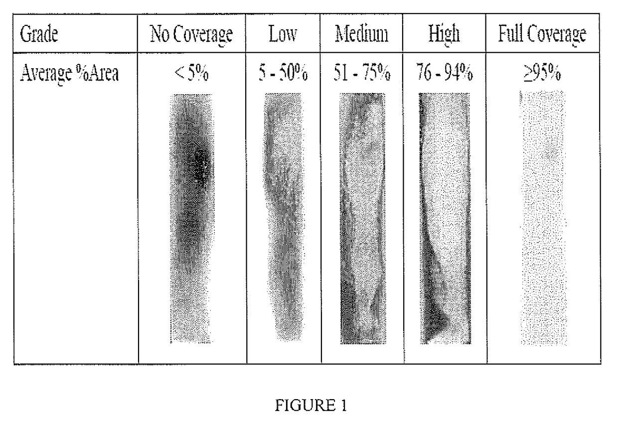
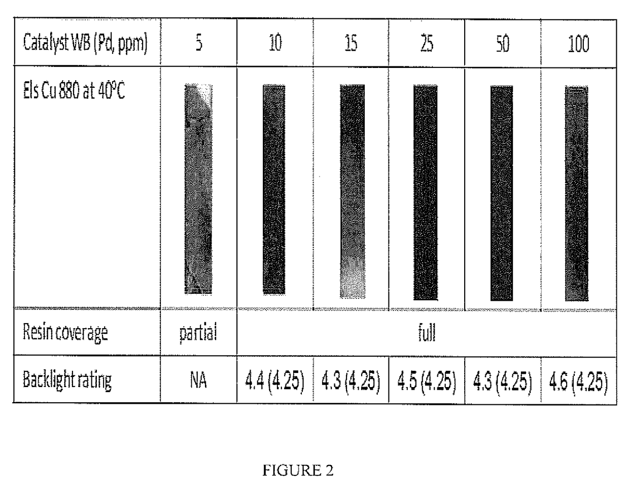
[0055]The properties of the catalyst were evaluated by observing test coupons plated by electroless copper plating according to the process described below. As the test coupon, conventional FR-4 laminate and SY-1141 from Shengyi were used. For surface coverage test, bare laminate was used. For backlight test, Cu clad laminate with inner layer copper was used.

(1) Test coupon was cut into 1×6 cm2 and its edges were sandblasted by SiC#240, then cleaned in RO (Reverse osmosis) water for several times and blown dried.

(2) Processed through the swelling, oxidizing, neutralizing, conditioning and microetching steps shown in Table 1.

(3) The test coupon was then dipped in the catalyst solution at 40° C. for 10 minutes at various pH values of 2.9 to 10.9 as shown in each example. The test coupon was washed with deionized water.

(4) Electroless copper plating was conducted at 35° or 40° C. for 15 minutes.

TABLE 1process flow for electroless Cu deposition testsTemper-Dur-Rinse atureati...

examples 1-4

alyst System from Different Palladium Salts

example 1

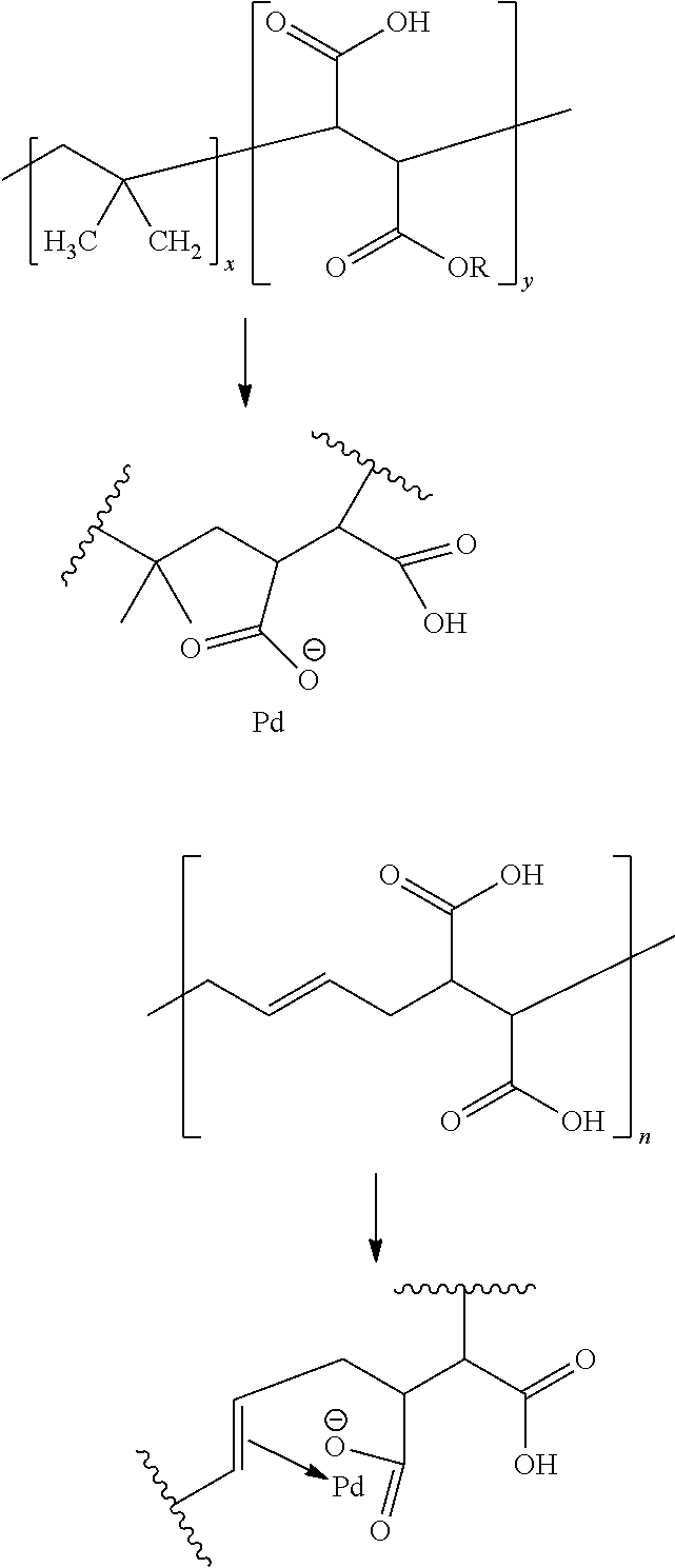
[0061]Step 1—Measured 2.38 g of poly (butadiene-maleic acid) 1:1 molar (Mw=10,000-15,000) solution (42%), and dissolved it with 25 ml of deionized (DI) water; mixed it with 780 ml of DI water into a 3 liter beaker with stirring; and added 1.0 g of dichlorodiammine palladium (II) into the solution with stirring. The pH was adjusted by NaOH to 3.0 to 4.0.

Step 2—Quickly injected 7 mL of freshly prepared 1.0 mol / L dimethylaminoborane (DMAB) into the above solution with strong stirring at 500 rpm using a magnetic stirrer and continued stirring for over 1 h and obtained Pd nanoparticles (Pd catalyst concentrate).

Step 3—For storing the prepared nanoparticles, the pH was adjusted to 9.0-9.5 after 3-4 hours from the injection of the reducing agent. The total volume was topped up to a final volume of 1 liter.

The ingredients of Pd concentrate are written below.

Pd catalyst concentrate:

Pd ion: 0.5 g / L

[0062]PBDMA as stabilizer: 1.0 g / L

DMAB: 7.0 mM

[0063]The Pd catalyst concentrate which was obtain...


PUM

PropertyMeasurementUnit
mole ratioaaaaaaaaaa
temperatureaaaaaaaaaa

Abstract

A solution including a precious metal nanoparticle and a polymer polymerized from at least two monomers, (1) a monomer having two or more carboxyl groups or carboxyl acid salt groups and (2) a monomer which has π electron-available features. The solution is useful for a catalyst of a process for electroless plating a metal on non-conductive surface.

Description

FIELD OF THE INVENTION[0001]The present invention relates to a catalyst solution comprising a precious metal nanoparticle, and more particularly, a catalyst solution comprising a precious metal nanoparticle stabilized by a specific compound useful in electroless metal plating of non-conductive substrates and used in the manufacture of electronic devices and decorative coating.BACKGROUND OF THE INVENTION[0002]Electroless metal deposition or plating is useful for the deposition of a metal or mixture of metals on a non-conductive or dielectric surface in the absence of an electric source. Plating on non-conductive or dielectric substrates is used in a variety of industries, including decorative plating and electronic device fabrication. One of the main applications is the manufacture of printed circuit boards. The electroless deposition of a metal on a substrate usually requires pretreatment or sensitization of the substrate surface to make the surface catalytic to the deposition proce...

Claims


Application Information

Patent Timeline
Patent Type & Authority Applications(United States)
IPC IPC(8): C23C18/31B01J23/50B01J35/00B01J31/06B01J23/44
CPCC23C18/31B01J31/06B01J23/50B01J35/0013B01J23/44C23C18/30H05K3/422C23C18/1879C23C18/1831C23C18/1834C23C18/1882C23C18/2066C23C18/206H05K3/185H05K3/381H05K2201/0257H05K2203/0766H05K2203/0783H05K2203/095B01J37/16B01J37/0219B01J23/38B01J37/0217C23C18/38
Inventor KWONG, SUK KWANZHOU, WEIJUANZHOU, WENJIACHAN, DENNIS CHIT YIUYEE, DENNIS KWOK-WAI
Owner ROHM & HAAS ELECTRONICS MATERIALS LLC
Learn More