These materials are usually physically hard and chemically
inert which make them difficult to structure by standard technologies including mechanical
machining or chemical
etching steps, e.g., standard top-down approach, including
ion beam structuring, electro beam writing or photo-
lithography.
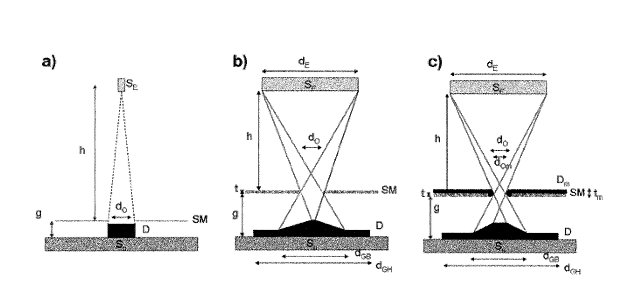
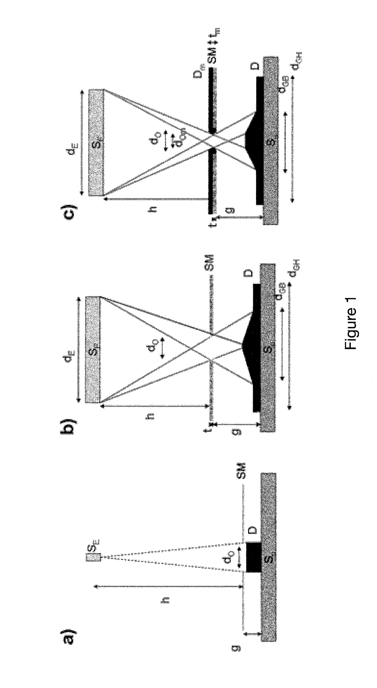
FIG. 1 presents some of the major problems associated with state of the art technology, which principally are [9] [10]:a) The blurring, which is a widening of the deposited pattern dimension compared to the stencil aperture size, due to the existing gap between the stencil and the substrate.
It is particularly problematic when deposited thickness is of the same order or higher than the aperture size in the case of nano-stencils.
This is no solution for a
chemical deposition technique in which reactive species decompose due to thermal heating, and it does not work with non volatile species.
In addition, deposition may take place on the mask top and side (image c), leading to clogging, due a deposit Dm that affects the aperture dimension (reduced from dO to dOm) and mask thickness (increased from t to tm).
Forgery and counterfeiting are problematic that organised societies have had to fight since the very beginning.
Everyone is aware of counterfeited products such as luxury goods, e.g. watches, handbags, jewels, softwares, DVDs, CDs, etc., but the plague also extends to new products such as pharmaceuticals or toys, where the problem is no longer only economical, but also impacting people's health or even putting their lives at risk.
. . ), up to very complex collaborative clouds or networks.
The societal plague associated with the lack of security of such systems (with identity hacking, frauds,
phishing scam, intrusion into privacy etc.
A further difficulty to overcome for an efficient technology is an economic one [38]: should it provide a product a totally unique, with an irreproducible signature, etc., there is no hope for its development if the tag price is higher than the likely loss of income through counterfeiting.
On one hand,
naked eye reading is a quite subjective and
time consuming solution at large scale and overt technology labels contain a very limited amount of information.
On the over hand, covert or
machine readable technologies require expensive / poor-mobility readers
Two different printing approaches are today available, either based on sequential (or serial) printing or based on parallel printing techniques:the first methods of serial printing usually suffer from
low resolution (thus containing low amount of information) or are
time consuming and poorly cost efficient if higher resolution (with micro or nano dots resolution) is targeted (like for Plixel Printing).
The time required to print a highly resolved etiquette / tag /
label is such that this method will never be suitable to address efficiently huge
mass production of
high security / high
information density.
This is an intrinsic limit of such serial printing technologies.
However, the
matrix production cost is usually very high and all the codes are identical, allowing neither flexibility nor variations on the tag (which is actually where the
traceability and possibly enhanced security lays).
Again, if the core technology is cracked (the matrix is duplicated), all the security associated with this solution is gone.
In the first case, a pattern can be seen by
naked eye, but does not provide any security mechanism.
When the ink secret composition is cracked, however, all the documents based on the technology can be forged.
Another drawback is related to recycling of such tags as mentioned in previous work (JPS62206695, JP2009276564) that very often contain rare or toxic elements.
Nevertheless, again these techniques suffer from most of the same intrinsic limits of printing methods with inks.
These methods are, however, very sensitive to the degradation of the object and identification of patterns can be quite
time consuming.
Furthermore, they require complex and time-consuming reader solutions.
Several other inventions are disclosed for polymers or easily etchable or machined materials such as resins (US2008248266, JPH04118690), but with limited lifetime due to poor mechanical and
chemical stability of the materials.
Materials with different refractive indexes are provided to achieve such an effect, leading either to limited effects or to very expensive
assembly manufacturing.
These solutions are however quite expensive and complex to realize.
On one hand, such solution claims that the
copper wires cannot be replicated, but the set-up is relatively simple and for sure cannot guarantee a huge number of different combinations.
On the other hand, the QR contains a very limited amount of information (black and white dots of
low resolution).
Furthermore, no security is tied to these codes that can thus be easily copied and reproduced or moved to different objects.
The bar codes ease of reading is also their main
weakness as anyone can
forge or counterfeit them.
Furthermore, such marks contain only very limited amount of information and when large numbers of objects are to be tracked (over 1 billion), the
system rapidly gets to its limits.
One solution is to further increase dot resolution or to add colour (JPS62206695, CN2448723), but this still yields intrinsic limits to security and anti-forgery issues.RFID (
radio frequency identification)
. . These RFID tags offer high reliability without contact reading method, but readers and codes themselves are getting quite expensive and with a
poor mobility.
However, these tags are quite expensive (15 cts for passive tags, 25 dollars for active tags [52]) and usually require bulky readers or
energy supply.
Furthermore, a huge quantity of tags (above 1'000) within a reader will lead to
confusion and misreading.
As a further
disadvantage we can also quote that RFID, or other purely
electronic systems, are usually providing poor security as tags can be moved from one product to another easily.
Finally, being a remote reading process, tracking of people wearing such tags on their products is a main limit to this technology as it disregards any
privacy policy.
However, these solutions cannot be applied to objects.
Furthermore, the over-increasing number of required passwords leads to poorly safe methodology to generate and store such passwords at
individual level.
More secure systems, involving hardware for PW generation, rely on additional manual time consuming endless
password checks that are a real hurdle to the end-user and cannot manage a huge number of secured transactions in a timely manner.
