Torque transmission device

a transmission device and torque technology, applied in the direction of friction clutches, mechanical devices, springs/dampers design characteristics, etc., can solve the problems of adverse influence on driving comfort, achieve effective reduction, eliminate torque fluctuations, and increase the staying force

Inactive Publication Date: 2016-07-28
SCHAEFFLER TECH AG & CO KG
View PDF2 Cites 3 Cited by
  • Summary
  • Abstract
  • Description
  • Claims
  • Application Information

AI Technical Summary

Benefits of technology

[0014]In another embodiment, the first ramp section and / or the second ramp section is positioned obliquely at an acute angle to the first and / or second ring section and / or to the first and / or second control disk section. The angle is preferably 5° to 30°, in particular 10° to 20°. This ensures that the ramp section surfaces can slide on each other, and that a high staying force can be provided to slow the pendulum mass at the same time.
[0015]In another embodiment, the control disk has a first friction surface on a side facing toward the pendulum mass and the pendulum mass has a second friction surface on the side facing toward the control disk; the two friction surfaces being designed to brace an oscillating torque of the pendulum mass relative to the spring damper when there is frictional contact. The oscillating torque, and thus the elimination of torque fluctuations, can be effectively reduced thereby in a simple way.
[0016]In another embodiment, a spring element is positioned between the control disk and the pendulum flange. The spring element is designed to provide a separation force to space the pendulum mass apart axially from the control disk, the spring element preferably being designed as a diaphragm spring. This design has the advantage that unwanted rubbing of the friction surfaces or unwanted contact of the control disk on the pendulum mass is reliably avoided.
[0017]In another embodiment, the control disk has a first control disk zone, a second control disk zone and a third control disk zone, the control disk zones being connected to each other, the first control disk zone being positioned parallel to the axis of rotation, the second control disk zone being positioned in a plane running perpendicular to the axis of rotation, while the third control disk zone is located radially outside bordering on the second control disk zone, the third control disk zone being positioned in a plane perpendicular to the axis of rotation and offset axially from the second control disk zone, the third control disk zone being positioned axially between the second control disk zone and the pendulum mass. This makes it possible to prevent the second control disk zone, in which the second ramp section is located, from coming into direct contact with the pendulum mass.

Problems solved by technology

Especially in internal combustion engines having cylinder deactivation, the torque transfer devices may be stimulated to unfavorable eigenmodes in the drivable range of the internal combustion engine, which may have an adverse influence on driving comfort.

Method used


Image

  • Torque transmission device
  • Torque transmission device
  • Torque transmission device

Examples


Embodiment Construction

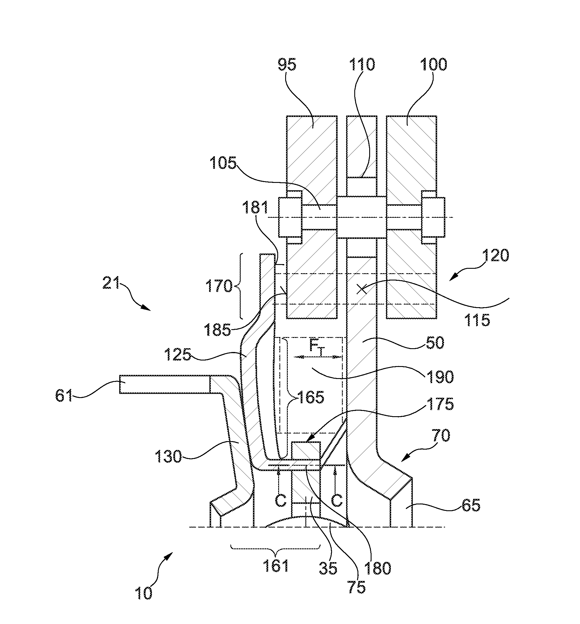
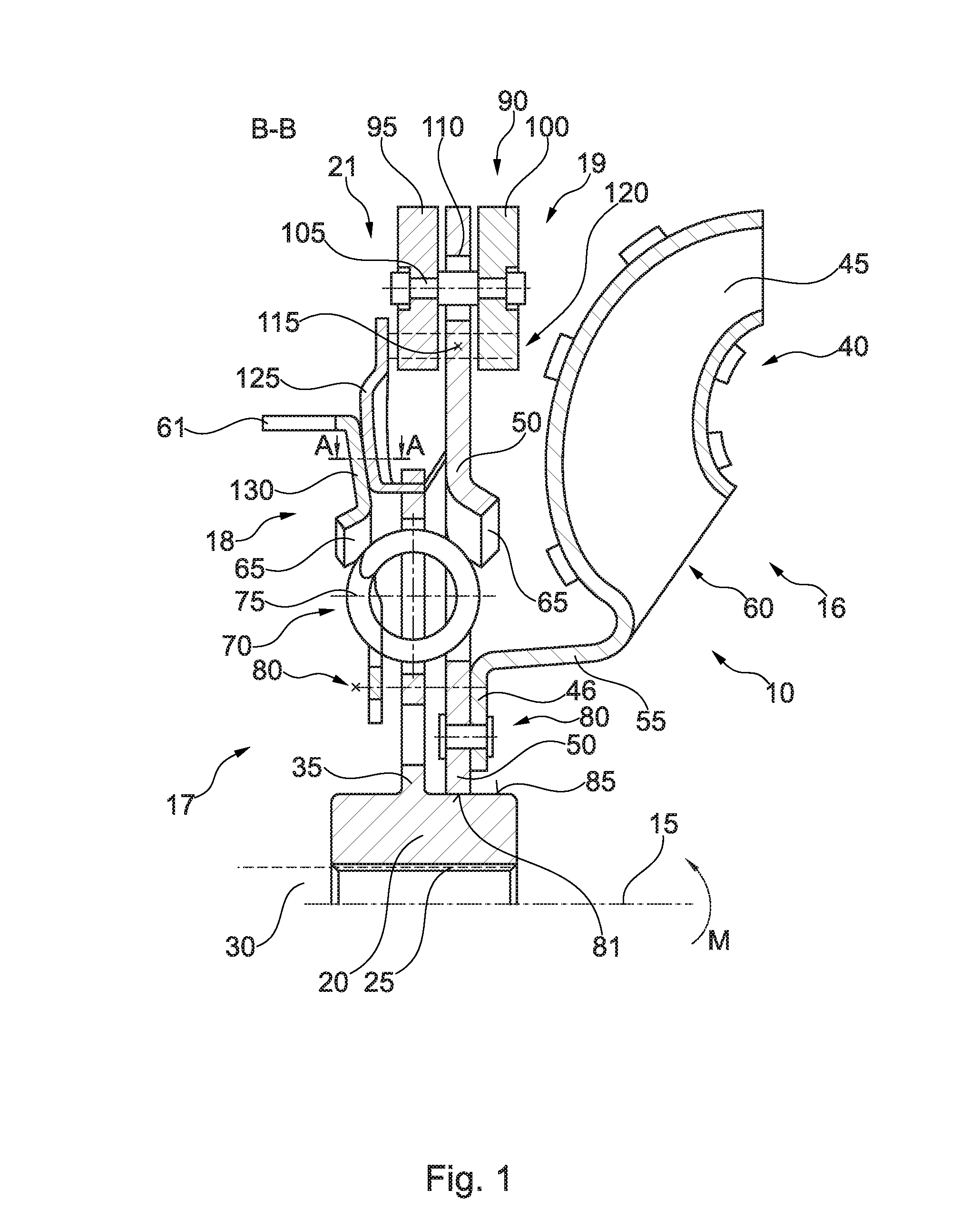
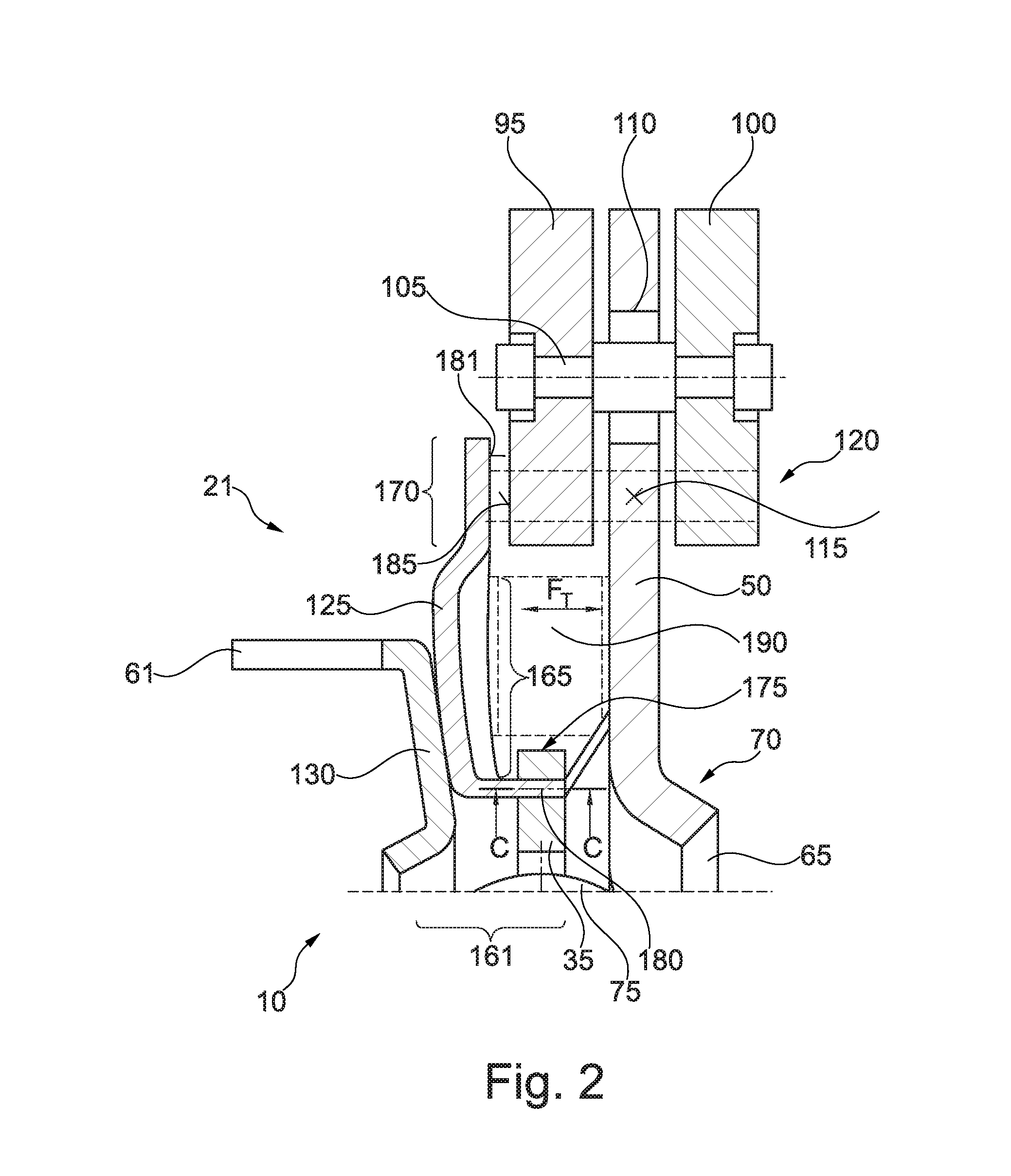
[0026]FIG. 1 shows a longitudinal section along a sectional plane B-B through the torque transfer device 10. FIG. 2 shows an enlarged detail of the longitudinal section of the torque transfer device 10 shown in FIG. 1. FIG. 3 shows a sectional view along a sectional plane A-A shown in FIG. 1 in a first operating state, and FIG. 4 shows a longitudinal section along the sectional plane A-A shown in FIG. 1 through the torque transfer device 10 in a second operating state. FIG. 5 shows a sectional view along a sectional plane C-C shown in FIG. 2 through the torque transfer device.

[0027]The torque transfer device 10 is mounted so that it can rotate around an axis of rotation 15. In this case, the torque transfer device 10 is part of a drivetrain of a motor vehicle. The torque transfer device 10 has an input side 16 and an output side 17. The input side 16 may be connected to a pump of a hydrodynamic converter 60, for example by means of a fluid stream. The output side 17 may be connected...


PUM


Abstract

A torque transfer device having a spring damper and a centrifugal pendulum, the torque transfer device being rotatable around an axis of rotation, the centrifugal pendulum having a pendulum flange and at least one pendulum mass, the pendulum mass being connected to the pendulum flange by means of a sliding block guide, the sliding block guide prescribing an oscillation path of the pendulum mass, the pendulum mass being designed to oscillate along the oscillation path, the pendulum flange being torsionally connected to the spring damper, the spring damper being designed to transfer a torque, a switching device being provided, the switching device being coupled with the spring damper, the switching device being designed to reduce the oscillating motion of the pendulum mass along the oscillation path at least partially when a predefined threshold value of the torque is exceeded.

Description

CROSS-REFERENCE TO RELATED APPLICATIONS[0001]The present application is the United States National Stage Application pursuant to 35 U.S.C. §371 of International Patent Application No. PCT / DE2014 / 200450, filed Sep. 8, 2014, and claims priority to German Patent Application No. 10 2013 219 429.3, filed Sep. 26, 2013, which applications are incorporated by reference in their entireties.FIELD OF THE INVENTION[0002]The invention relates to a torque transfer device.BACKGROUND OF THE INVENTION[0003]Torque transfer devices having a spring damper, a centrifugal pendulum and a converter clutch are known. The torque transfer device in such cases is designed to transfer a torque coming from an internal combustion engine to a gear unit, while compensating for fluctuations in the torque. This enables the drivetrain to be designed for especially low noise, while at the same time opening up the possibility of operating internal combustion engines at a lower speed. This enables the fuel consumption o...

Claims


Application Information

Patent Timeline
Patent Type & Authority Applications(United States)
IPC IPC(8): F16F15/123
CPCF16F15/12353F16D13/58F16F15/121F16F15/145F16F2230/0052Y10T74/2128
Inventor MAIENSCHEIN, STEPHAN
Owner SCHAEFFLER TECH AG & CO KG
Why Eureka
Try Eureka