
Air vehicle assembly and an associated control system and method

a technology for air vehicles and control systems, applied in the field of air vehicles, can solve the problems of inferior range of ducted fan uav to fixed wing uav, relatively short duct span, and inability to survive, etc., to achieve greater endurance, greater range, and greater range

Active Publication Date: 2007-05-10
THE BOEING CO
View PDF31 Cites 42 Cited by
  • Summary
  • Abstract
  • Description
  • Claims
  • Application Information

AI Technical Summary

Benefits of technology

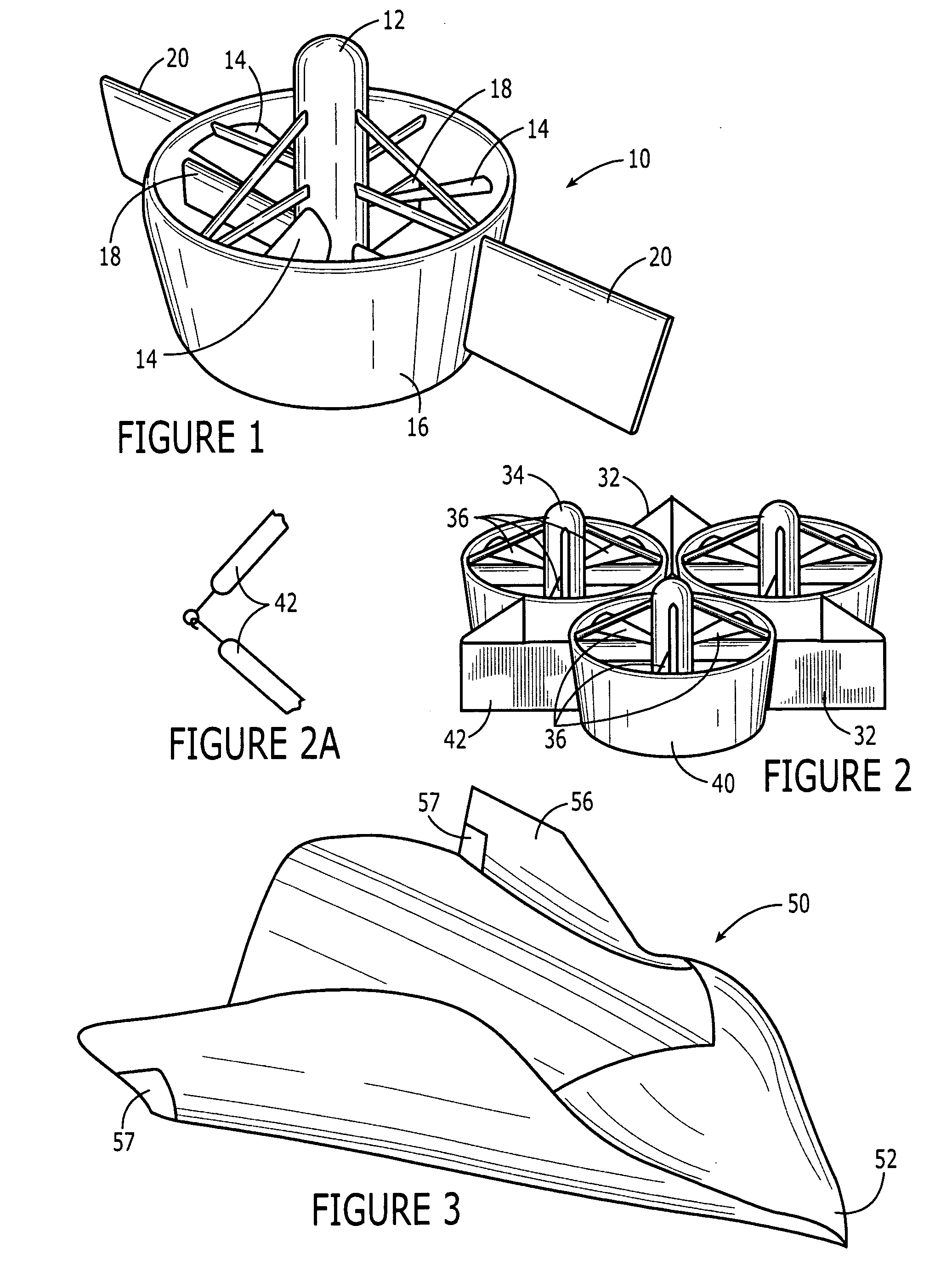
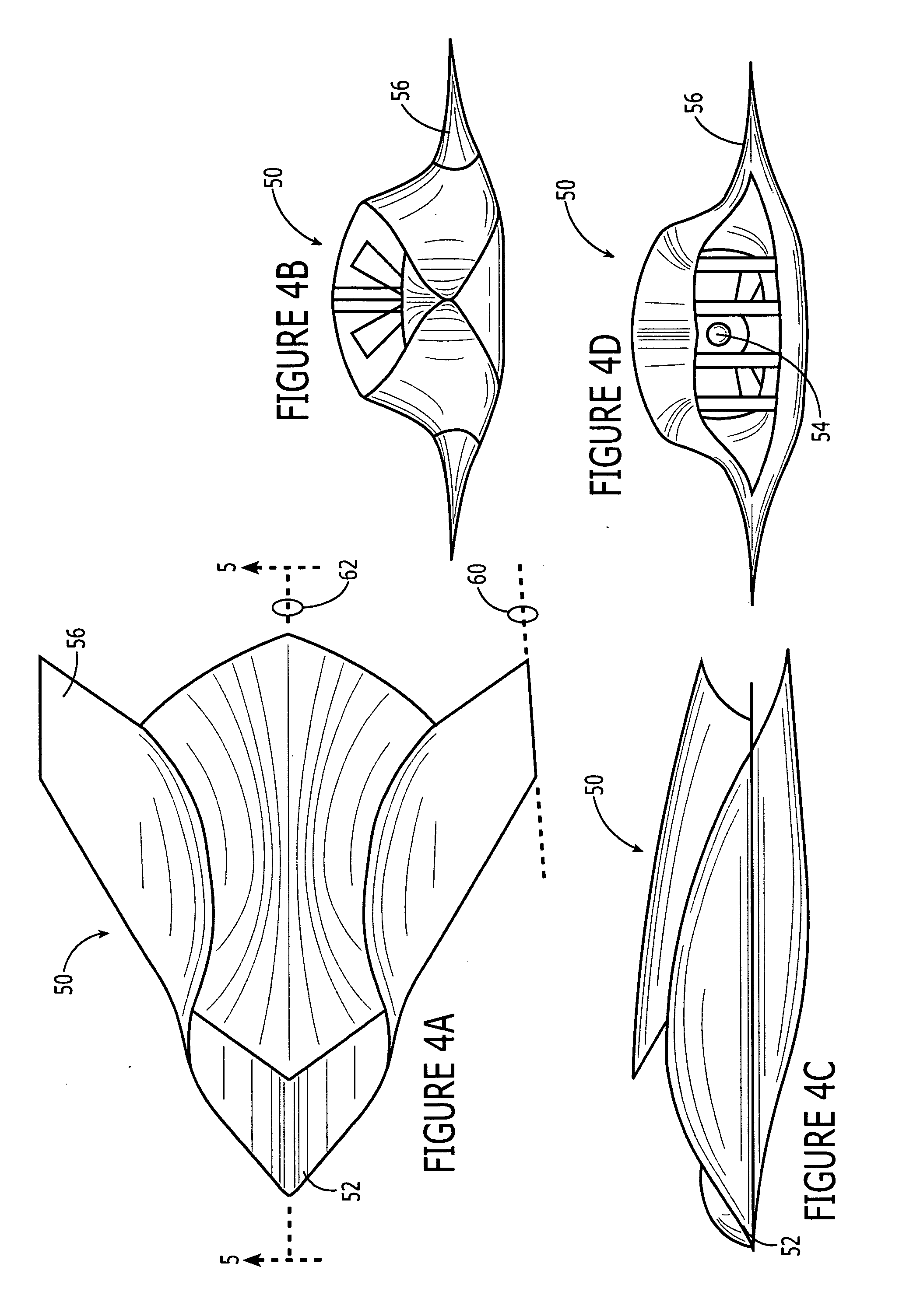
[0006] An air vehicle assembly and a corresponding method for launching an air vehicle assembly are provided, along with corresponding control systems and methods which address at least some of the drawbacks identified above with respect to conventional UAVs, such as those UAVs capable of vertical take-off and landing. In one aspect of this invention, an air vehicle assembly is provided that may include a plurality of air vehicles, such as three or more air vehicles, that are releasably joined to one another during a portion of the flight, such as during take-off and landing. The air vehicle assembly of this aspect may permit the individual air vehicles to have a greater range and higher endurance than at least some comparable UAVs that are similarly designed for vertical take-off and landing. In this regard, the plurality of air vehicles that are releasably joined to one another, such as during take-off and landing, can rely upon and assist one another during the vertical take-off and landing while being designed to have a greater range and higher endurance following the transition to forward flight, either while remaining coupled to or following separation from the other air vehicles.
[0013] By forming an air vehicle assembly, the air vehicle assembly of one embodiment can, as a whole, be designed for vertical take-off and landing regardless of whether any of the individual air vehicles could vertically take-off and land on its own. As such, the air vehicles can be designed to have a greater range and higher endurance even if those design modifications would render the air vehicle incapable of vertical take-off and landing by itself so long as the air vehicle in combination with the other air vehicles of the air vehicle assembly are collectively able to vertically take-off and land. Moreover, the capability of flight in the line abreast configuration also effectively extends the range of the air vehicle assembly as opposed to any air vehicle by itself as a result of the wing span when considered on a collective basis. Thus, the air vehicles of embodiments to the present invention may access targets in regions that are further from their base, while still being capable of controlled flight as a result of the control system that factors in the respective states of the other air vehicles while the air vehicles are coupled to one another.

Problems solved by technology

However, the ducted fan UAV is not particularly survivable and generally has a larger radar cross section and acoustic signature than desired.
In addition, the range of the ducted fan UAV is inferior to a fixed wing UAV as a result of its relatively short wing span.
In this regard, the relatively short span of the duct translates into greater drag and correspondingly shorter range in comparison to a comparable fixed wing UAV that is designed for a more conventional take-off and landing.
The range and signature of the ducted fan UAV is also impaired by the inclusion of substantial control electronics as are required to provide three-axis control of the ducted fan UAV while in a hovering position.

Method used


Image

  • Air vehicle assembly and an associated control system and method
  • Air vehicle assembly and an associated control system and method
  • Air vehicle assembly and an associated control system and method

Examples


Embodiment Construction

[0025] The present inventions now will be described more fully hereinafter with reference to the accompanying drawings, in which some, but not all embodiments of the inventions are shown. Indeed, these inventions may be embodied in many different forms and should not be construed as limited to the embodiments set forth herein; rather, these embodiments are provided so that this disclosure will satisfy applicable legal requirements. Like numbers refer to like elements throughout.

[0026] According to embodiments of the present invention, an air vehicle assembly is provided that includes a plurality of air vehicles, such as two or more air vehicles, with each air vehicle being releasably joined to another air vehicle. The air vehicle assembly also includes a control system for at least partially controlling operation of the air vehicles such that the air vehicles can take off, vertically or otherwise, while said air vehicles are releasably joined to one another, such as in a line-abrea...


PUM


Abstract

An air vehicle assembly and a corresponding method for launching an air vehicle assembly are provided, along with corresponding control systems and methods. The air vehicle assembly may include a plurality of air vehicles releasably joined to one another during a portion of the flight, such as during take-off and landing. By being releasably joined to one another, such as during take-off and landing, the air vehicles can rely upon and assist one another during the vertical take-off and landing while being designed to have a greater range and higher endurance following the transition to forward flight, either while remaining coupled to or following separation from the other air vehicles. By taking into account the states of the other air vehicles, the control system and method also permit the air vehicles of an air vehicle assembly to collaborate.

Description

FIELD OF THE INVENTION [0001] The present invention relates generally to air vehicles and, more particularly, to air vehicles that are capable of being releasably joined to other air vehicles as well as an associated control system and method. BACKGROUND OF THE INVENTION [0002] Unmanned air vehicles (UAVs) are becoming increasingly prevalent and the performance requirements desired of UAVs are similarly increasing. In this regard, it is desired that UAVs have a long range and high endurance in order to carry out operations far from their base. Additionally, it is desirable for some UAVs to be capable of being launched from and recovered off of relatively small ships. Still further, it is desirable for the speed of UAVs to be increased while the signature of the UAVs is decreased such that UAVs become more survivable. [0003] While UAVs that are capable of a conventional take-off and landing have been developed, some applications demand a vertical take-off and landing capability, such...

Claims


Application Information

Patent Timeline
Patent Type & Authority Applications(United States)
IPC IPC(8): B64C29/00B64C37/02
CPCB64C39/024B64C2201/027B64C2201/028B64C2201/088B64C2201/104B64C2201/108B64C2201/126B64C2201/162B64C2201/165B64D5/00B64U10/25B64U30/10B64U30/20B64U2101/00B64U50/14B64U80/82B64U10/20
Inventor SPEER, THOMAS E.JONES, RICHARD D.
Owner THE BOEING CO
Learn More