
Improved device for discharging pretreated biomass from higher to lower pressure regions

a technology of discharging device and biomass, which is applied in the direction of finely divided material pretreatment, supercritical condition process, water/steam pretreatment, etc., can solve the problems of disintegration of waste paper fibres, inability to provide safe transfer of aqueous slurry, and inability to discharging pretreated biomass from higher to lower pressure regions. achieve the effect of improving the yield of target fermentation substances, reducing the concentration of furfural, and increasing the yield of target substances

Active Publication Date: 2016-07-28
INBICON AS
View PDF1 Cites 6 Cited by
  • Summary
  • Abstract
  • Description
  • Claims
  • Application Information

AI Technical Summary

Benefits of technology

This patent describes a device and method for processing fibrous lignocellulosic biomass. The invention has two main benefits: it reduces the loss of valuable carbon sources in the biomass, such as C5-sugars, and it reduces the concentration of furfural in the liquid fraction, which is a by-product of the processing. These two effects combined result in higher yields of target fermentation substances, leading to improved economics of the biomass processing.

Problems solved by technology

Discharge of pretreated biomasses from high pressure regions to subsequent processing at lower or atmospheric pressure presents a technical problem that has previously been solved by three general approaches.
Such a pulper comprises a vessel comprising in a lower part a rotator or agitator in the form of a conical screw which imparts physical impact to the waste paper thereby resulting in a disintegration of the waste paper fibres.
The apparatus disclosed in U.S. Pat. No. 4,460,132 comprises no means for being connected with a pressurized biomass pretreatment device and is therefore not suitable for use for discharging pretreated biomass from higher to lower pressures.
The apparatus disclosed in U.S. Pat. No. 4,725,295 does not provide any means allowing safe transfer of an aqueous slurry of a biomass comprising considerably amounts of liquid water being present at super atmospheric pressures from this super atmospheric region to a low pressure region.
Due to the presence of this overflow channel, the separator disclosed in WO2009 / 137867 A1 will not be suitable for processing sludge being present at superatmospheric pressures.
Due to the arrangement of the stirrer at the top, this apparatus will not be suitable for providing stirring of a slurry of a solid material entering the apparatus and specifically this apparatus will not be suitable for transferring pretreated biomass from higher to lower pressure regions.
Due to the presence of these fixed anti-rotation members and the viscous nature of aqueous slurries of lignocellulosic biomass, the apparatus disclosed in U.S. Pat. No. 6,428,591 B1 will not be suitable for processing lignocellulosic biomass because of clogging risks.
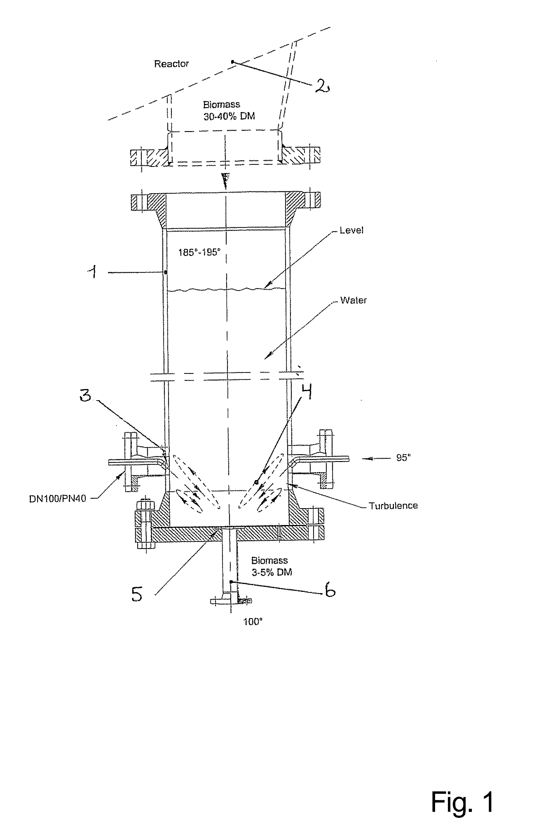
It has been found that when using a device disclosed in WO 2009 / 147512 A2 for transferring a discharging hydrothermally pretreated biomass from higher to lower pressure regions, an undesirably high percentage of C5-sugars, such as xylan species, originally present in the lignocellulosic material is inevitably lost into the liquid phase of slurry.
This in turn causes difficulties in subsequent processing steps.
Furthermore, as a consequence of sedimenting clumps of pretreated material accumulating on the bottom and sides of the reactor, a significant incidence of “lignin charring” may occur, which introduces a tendency for “clogging” of filters and pumps used in subsequent processing steps.

Method used


Image

  • Improved device for discharging pretreated biomass from higher to lower pressure regions
  • Improved device for discharging pretreated biomass from higher to lower pressure regions
  • Improved device for discharging pretreated biomass from higher to lower pressure regions

Examples


example

[0171]Experiments were performed at the Inbicon demonstration plant in Kalundborg, Denmark.

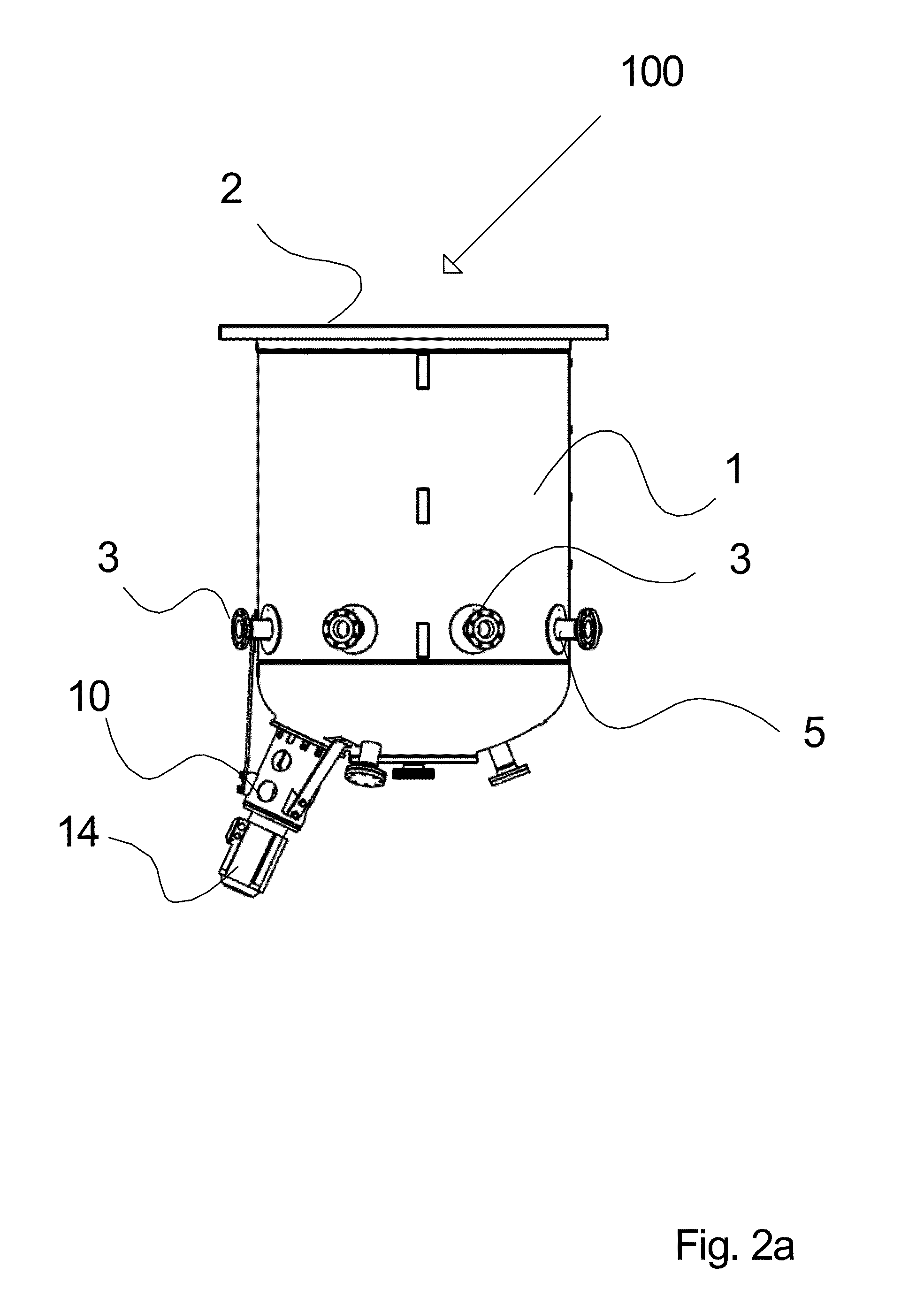
[0172]This example illustrates a process for hydrothermal pretreatment and subsequent discharge of a lignocellulosic biomass into a lower atmospheric pressure region using a prior art hydrocyclone of the type disclosed in WO 2009 / 147512 A2, however modified by incorporating mechanical agitation means comprising an agitation element arranged in the interior of the vessel of that hydrocyclone in a lower part thereof.

[0173]The experiments were performed in two different modes; one mode in which the agitation means were not applied; and another mode in which the agitation means were applied.

Hydrothermal Pretreatment of the Lignocellulosic Biomass

[0174]Lignocellulosic biomass in the form of wheat straw (cut to an average length of approximately 40 mm) was continuously loaded onto a reactor for hydrothermal pretreatment of biomass at 185-200° C. for 20 min at a rate of 1500 kg / hour. The reactor comp...


PUM

PropertyMeasurementUnit
Temperatureaaaaaaaaaa

Abstract

Provided is a discharge device for discharging pretreated biomass from a pressurized reactor. The device comprises:a vessel having an opening to a high pressure region at the top, and configured to be connected with a pressurized biomass pretreatment device;one or more inlet openings situated along the sides of the vessels through which water or liquid may be added;an orifice or valve at a lower part of said vessel, said orifice or valve being configured to eject pretreated biomass, optionally into a pipeline.The discharge device is characterised in that it comprises mechanical agitation means, said agitation means comprising an agitation element arranged in the interior of said vessel at a lower part of said vessel, and being configured to provide agitation of the content of said vessel, wherein said agitation means being adapted to withstand a pressure in the interior of a said vessel of 10 bar or more. The agitation means provides for a temperature equalization within a specific vertical range of heights of an aqueous slurry present in said vessel, thereby eliminating disadvantages of the prior art devices and methods.

Description

FIELD OF THE INVENTION[0001]The present invention relates to a discharge device and a method for discharging biomass, that has been subject to pressurized treatments, into lower or atmospheric pressure regions. Moreover, the present invention relates to an apparatus comprising such discharge device in combination with a pretreatment reactor. Furthermore, the present invention relates to use of such a discharge device for transferring pretreated biomass from higher to lower pressures.BACKGROUND OF THE INVENTION[0002]An intense interest has arisen in fermentation and gasification of carbohydrate-rich biomass to provide alternatives to petrochemical sources for fuels, livestock feeds and for organic chemical precursors.[0003]Lignocellulosic biomasses including industrial and agricultural wastes have proved particularly interesting as carbohydrate sources.[0004]For lignocellulosic biomasses subject to processing by enzymatic hydrolysis, pretreatment is generally required in order to sep...

Claims


Application Information

Patent Timeline
IPC IPC(8): D21C1/10D21C1/02
CPCD21C1/02D21C1/10C10L5/44C10L9/086B01J3/002B01J3/008B01J3/02B01J3/04B01J2219/00058B01J2219/00065B01J2219/00067B01J2219/00162B01J2219/00177B01J2219/0018B01J2219/00182B01J2219/00189C12P2201/00Y02E50/10Y02E50/30
Inventor DOHRUP, JESPERESKESEN, BRIANMOGENSEN, KIT KELLEBJERG
Owner INBICON AS
Learn More