
Method for manufacturing galvanized steel sheet

Active Publication Date: 2015-11-05
JFE STEEL CORP
View PDF0 Cites 0 Cited by
  • Summary
  • Abstract
  • Description
  • Claims
  • Application Information

AI Technical Summary

Benefits of technology

The present invention is about a method for making a galvanized steel sheet with a good surface appearance and no coating or pressing flaws. This method is particularly useful for high-Si-containing steel sheets, which are difficult to galvanize. Using this method can increase the yield ratio of the galvanized steel sheet manufacturing process.

Problems solved by technology

On the other hand, in the case where a galvanized steel sheet or a galvannealed steel sheet is manufactured using a high-strength steel sheet containing a large amount of Si therein as a base steel sheet, the following problems exist.
Such oxides decrease the wettability of the base steel sheet with molten zinc, which results in coating defects at galvanizing.
In addition, even in the case where coating defects do not occur, there is a problem of decrease in coating adhesiveness.
Moreover, such oxides significantly decrease an alloying rate in an alloying process after galvanizing.
As a result, there is a significant decrease in productivity of galvannealed steel sheet.
On the other hand, in the case where alloying treatment is performed at a high temperature in order to achieve high productivity, since there is a problem of decrease in powdering resistance, it is difficult to achieve efficient productivity and sufficient powdering resistance at the same time.
In addition, since there is a decrease in stability of residual γ phase by performing an alloying treatment at a high temperature, there is a decrease in effect of adding Si.
As described above, it is very difficult to manufacture a high-strength galvanized steel sheet having satisfactory mechanical properties and coating quality at the same time.

Method used


Image

  • Method for manufacturing galvanized steel sheet
  • Method for manufacturing galvanized steel sheet

Examples


example 1

[0077]The present invention will be described based on examples hereafter.

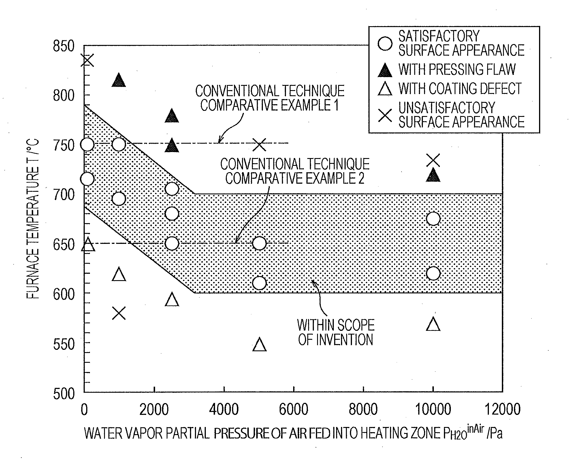
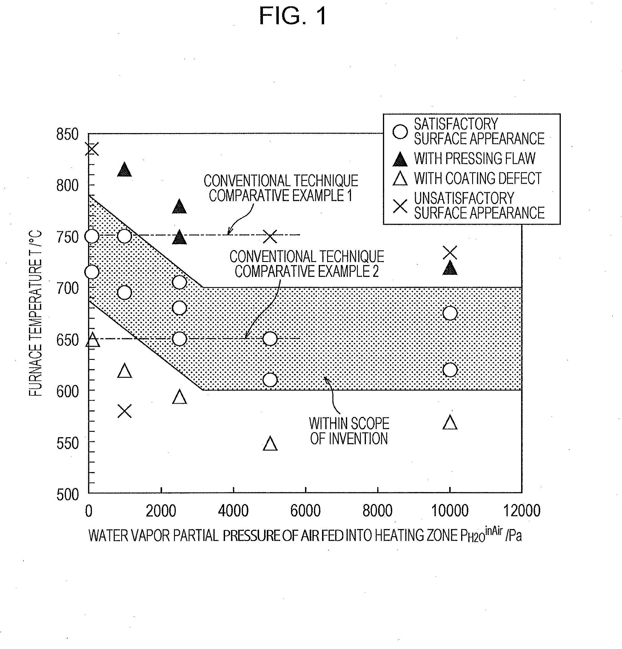
[0078]Slabs having chemical compositions given in Table 1 were heated at a temperature of 1260° C. for 60 minutes in a heating furnace, hot-rolled into a thickness of 2.8 mm, and then coiled at a temperature of 540° C. Subsequently, after scale had been removed by pickling, the coiled steel sheets were cold-rolled into a thickness of 1.6 mm. Then, a heat treatment was performed under the conditions given in Table 2 using a DFF-type CGL having divided heating zones. After heat treatment, the steel sheets were dipped in an Al-containing Zn bath having a temperature of 460° C. in order to obtain galvanized steel sheets (GI), and then the galvanized steel sheets were subjected to alloying treatment in order to obtain galvannealed steel sheets (GA). Here, the Al concentration in the bath was 0.10% to 0.20%, and the coating weight was controlled to be 45 g / m2 by using a gas wiping method. The alloying treatment was ...


PUM

PropertyMeasurementUnit
Temperatureaaaaaaaaaa

Abstract

A method for manufacturing a galvanized steel sheet includes heating a base steel sheet in a heating zone such that the surface of the base steel sheet is heated at a temperature of 600° C. or higher and 790° C. or lower while a furnace temperature T° C. in the heating zone of an annealing furnace is controlled based on the water vapor partial pressure PH2Oin Air of air fed into the heating zone, the base steel sheet having a chemical composition consisting of, by mass %, C: 0.05% or more and 0.25% or less, Si: 0.1% or more and 3.0% or less, Mn: 0.5% or more and 3.0% or less, P: 0.001% or more and 0.10% or less, Al: 0.01% or more and 3.00% or less, S: 0.200% or less, and the balance being Fe and inevitable impurities, heating the base steel sheet in the heating zone such that the surface of the base steel sheet is heated at a temperature of 630° C. or higher and 850° C. or lower in an atmosphere containing hydrogen gas having a partial pressure PH2 of 1000 Pa or more and 50000 Pa or less, water vapor gas having a partial pressure PH2O of 610 Pa or less, and the balance being N2 and inevitable impurities, and galvanizing the base steel sheet.

Description

TECHNICAL FIELD[0001]The present invention relates to a method for manufacturing a galvanized steel sheet whose base steel sheet is a Si-containing high-strength steel sheet, in particular, a method for manufacturing a galvanized steel sheet having good surface appearance without surface defects such as coating defects or pressing flaws and having excellent coating adhesiveness.BACKGROUND ART[0002]Nowadays, coated steel sheets in which corrosion resistance is given to the base steel sheet, in particular, galvanized steel sheets or galvannealed steel sheets which are excellent in terms of corrosion resistance, are used in the fields of, for example, automobile, domestic electric appliance, and building material.[0003]Generally, a galvanized steel sheet is manufactured using the following method. First, a steel sheet produced by hot-rolling and cold-rolling a steel slab, or followed by heat treatment, is annealed for recrystallization in a non-oxidizing atmosphere or a reducing atmosp...

Claims


Application Information

Patent Timeline
IPC IPC(8): C23C2/02C23C2/40C21D9/46C21D6/00C22C38/60C22C38/58C22C38/54C22C38/50C22C38/48C22C38/44C22C38/42C22C38/38C22C38/34C22C38/32C22C38/28C22C38/26C22C38/22C22C38/20C22C38/16C22C38/14C22C38/12C22C38/06C22C38/04C22C38/02C23C2/06
CPCC23C2/02C22C38/02C23C2/40C21D9/46C21D6/004C21D6/005C21D6/008C22C38/60C22C38/58C22C38/54C22C38/50C22C38/48C22C38/44C22C38/42C22C38/38C22C38/34C22C38/32C22C38/28C22C38/26C22C38/22C22C38/20C22C38/16C22C38/14C22C38/12C22C38/06C22C38/04C23C2/06C23C2/28C22C18/04C22C38/00C21D1/74C21D9/561C23C2/0222C23C2/0038C23C2/024C23C2/0224
Inventor TANAKA, MINORUSUZUKI, YOSHITSUGUMIYATA, MAINAGATAKI, YASUNOBU
Owner JFE STEEL CORP
Learn More