
Anti-corrosion coatings

Active Publication Date: 2015-09-03
UNIVERSITY OF ULSTER
View PDF4 Cites 8 Cited by
  • Summary
  • Abstract
  • Description
  • Claims
  • Application Information

AI Technical Summary

Benefits of technology

The current invention provides a coating with improved corrosion resistance compared to un-doped graphene. The planar morphology of the coating with nanosheet edges that are easier to oxidize than the basal plane leads to better protection against corrosion. The coatings have a high charge transfer resistance and can lower corrosion current density and induce a more positive voltage, making them ideal for various applications such as electronics, sensors, and batteries. The silicon incorporation in the coatings further enhances their corrosion protection properties.

Problems solved by technology

The development of active corrosion protection systems for metallic substrates is an issue of prime importance for many industrial applications.
The use of refined metals is widespread, but such metals can frequently be chemically reactive, limiting their use or requiring protective coatings.
Corrosion of metals is a significant destructive process, resulting in huge economic losses, especially in the aerospace, automotive, and petroleum industries.
An intense effort is underway to find coatings that inhibit the process of metal corrosion, a problem costing US industries more than $200 billion annually.
Such conventional approaches suffer from a variety of limitations, such as susceptibility to heat damage, necessity of thick coatings, cost, formation of waste products, etc.
However, these protective coatings have their limitations.
Thiolated self-assembled monolayers (SAMs) can only be assembled onto some metals (e.g., gold and copper) and do not withstand temperatures higher than −100° C. Polymeric coatings are relatively thick and may significantly change the physical properties of the underlying material.
However, when the barrier is damaged and the corrosive agents penetrate the metal surface the coating system cannot stop the corrosion process.
However, this product is well-known to be toxic and carcinogenic and is now prohibited on end products and highly regulated on industrial lines by European Community directives (VUH and RoHS).
However, the existing graphene-coating technology has drawbacks.
For example, the growth and / or transfer processes of graphene inevitably result in pinholes, defects or cracks in the film.
This causes problems with corrosion, for example oxidative corrosion, at edges, defects and / or grain boundaries.
For example, the metal substrate corrodes under the coating at points where there are pinholes in the graphene film.

Method used


Image

  • Anti-corrosion coatings
  • Anti-corrosion coatings
  • Anti-corrosion coatings

Examples


examples

[0080]In this work we have examined the behaviour of bare copper , annealed copper, graphene coated copper and Si incorporated copper in saline solution as well as after exposure to air at elevated temperature of 200° C. for 1 hour.

[0081]Sample Preparation

[0082]A SEKI Technotron ECR-MPCVD system (2.45 GHz, 1.5 KW), was used to deposit Si incorporated graphene films. Briefly the system was pumped down to base pressure of 2.8 10-5 Torr and was operated in ECR mode. Cu foils 25 μm thick (99.999%, Alfa Aesar No. 10950) were initially etched for 3-4 minutes at room temperature in an Ar plasma using microwave power of 100W. Then the temperature was raised to approximately 900° C. and the samples are heated in a background pressure of 40 Torr of N2.

[0083]Graphene and silicon incorporated graphene were synthesised in a gas mixture of methane and argon and TMS (tetramethylsilane—Si(CH3)4 with gas flow rates of 6, 3 and 0 to 10 sccm (standard cubic centimetres per minute) respectively. Deposi...


PUM

PropertyMeasurementUnit
Fractionaaaaaaaaaa
Fractionaaaaaaaaaa
Fractionaaaaaaaaaa

Abstract

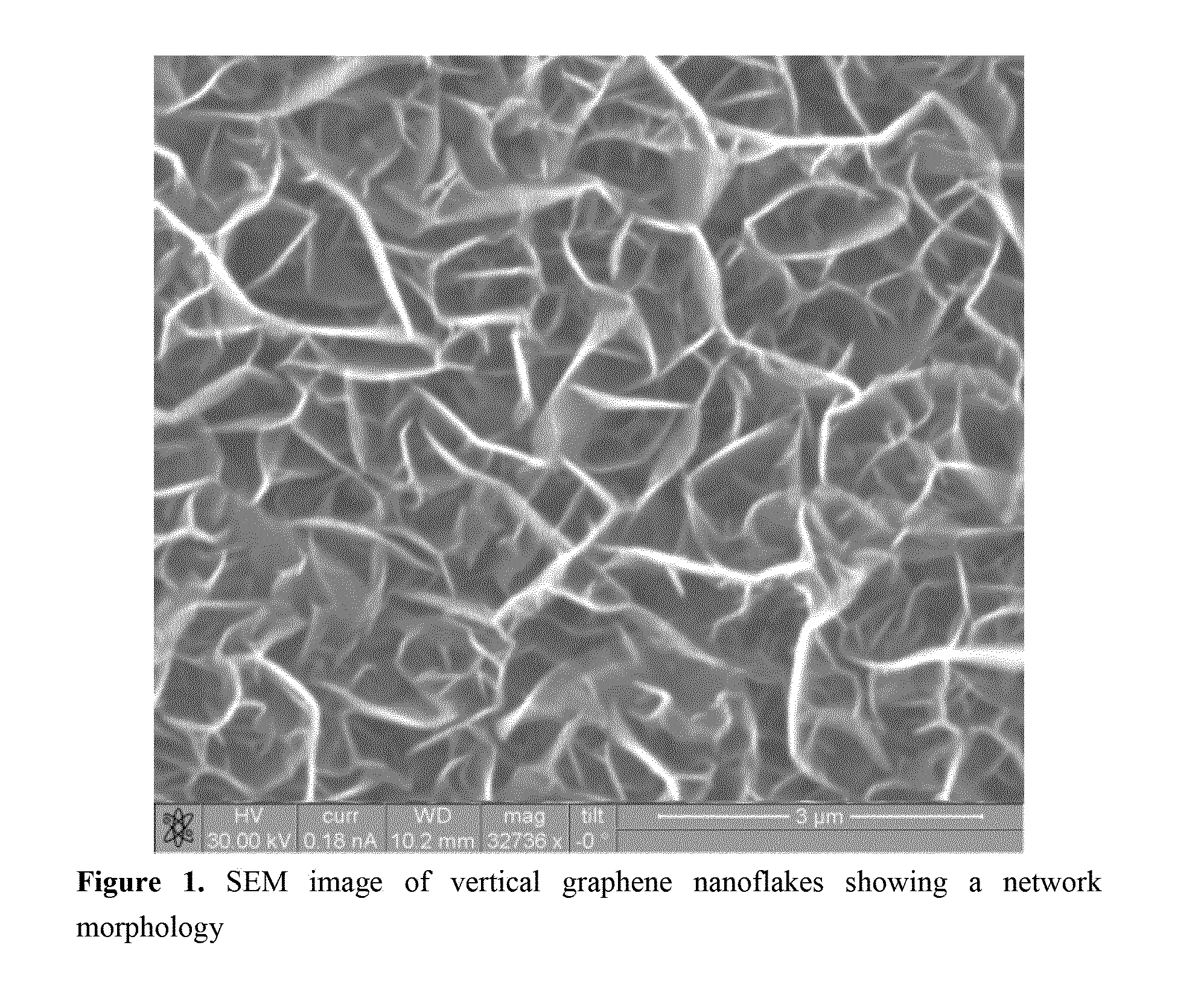
A coating comprising silicon-doped graphene layers wherein the graphene is in the form of horizontally-aligned graphene nanosheets.

Description

FIELD OF THE INVENTION[0001]The present invention relates to protective coatings, specifically to protective silicon-doped graphene coatings for use on metals, their production and uses. The invention also relates to a method of inhibiting corrosion comprising the formation of said coatings and the use of said coatings in the inhibition of corrosion, particularly in the reduction of oxidative corrosion.BACKGROUND[0002]The development of active corrosion protection systems for metallic substrates is an issue of prime importance for many industrial applications. The use of refined metals is widespread, but such metals can frequently be chemically reactive, limiting their use or requiring protective coatings. Protecting the surface of such metals has developed into a significant industry.[0003]Corrosion of metals is a significant destructive process, resulting in huge economic losses, especially in the aerospace, automotive, and petroleum industries. An intense effort is underway to fi...

Claims


Application Information

Patent Timeline
IPC IPC(8): C09D5/08C23C16/26
CPCC09D5/084C23C16/26C01B32/186C01B2204/04C01B2204/30Y10T428/24975Y10T428/30
Inventor PAPAKONSTANTINOU, PAGONA
Owner UNIVERSITY OF ULSTER
Learn More