Eureka AIR delivers breakthrough ideas for toughest innovation challenges, trusted by R&D personnel around the world.

Brake assembly and a method of operating a brake assembly

a technology of brake assembly and brake assembly, which is applied in the direction of braking system, stopper details, dynamo-electric machines, etc., can solve the problems of increasing wind resistance and noise, and achieve the effects of dissipating heat, preventing the breakdown of tyre material, and inhibiting heat conduction

Active Publication Date: 2015-07-23
MESSIER DOWTY
View PDF6 Cites 12 Cited by
  • Summary
  • Abstract
  • Description
  • Claims
  • Application Information

AI Technical Summary

Benefits of technology

This patent describes a brake assembly for aircraft landing gear that uses electromagnetic coils to induce a rotation force on the rim, which then reduces loads associated with spin-up and spring back of the aircraft landing gear. The design of the brake assembly includes a stator that aligns with the rim to maximize the inductive coupling between the stator and the rim, as well as an insulating material to prevent breakdown of the tire due to the rim's interaction with the stator. Additionally, the brake assembly includes a friction brake for further redundancy and emergency braking. The use of electromagnetic coils also allows for the application of a current to induce a rotation force on the rim to increase its angular velocity before touch down of the aircraft, reducing loads associated with spin-up and spring back.

Problems solved by technology

In addition, the brake assembly in an aircraft landing wheel occupies substantially all of the wheel cavity, meaning that any electric taxi solution involves mounting a prime mover external to the wheel cavity which takes up valuable space when the landing gear is retracted into the fuselage, and increases wind resistance and noise when the landing gear is deployed.

Method used


Image

  • Brake assembly and a method of operating a brake assembly
  • Brake assembly and a method of operating a brake assembly
  • Brake assembly and a method of operating a brake assembly

Examples


Embodiment Construction

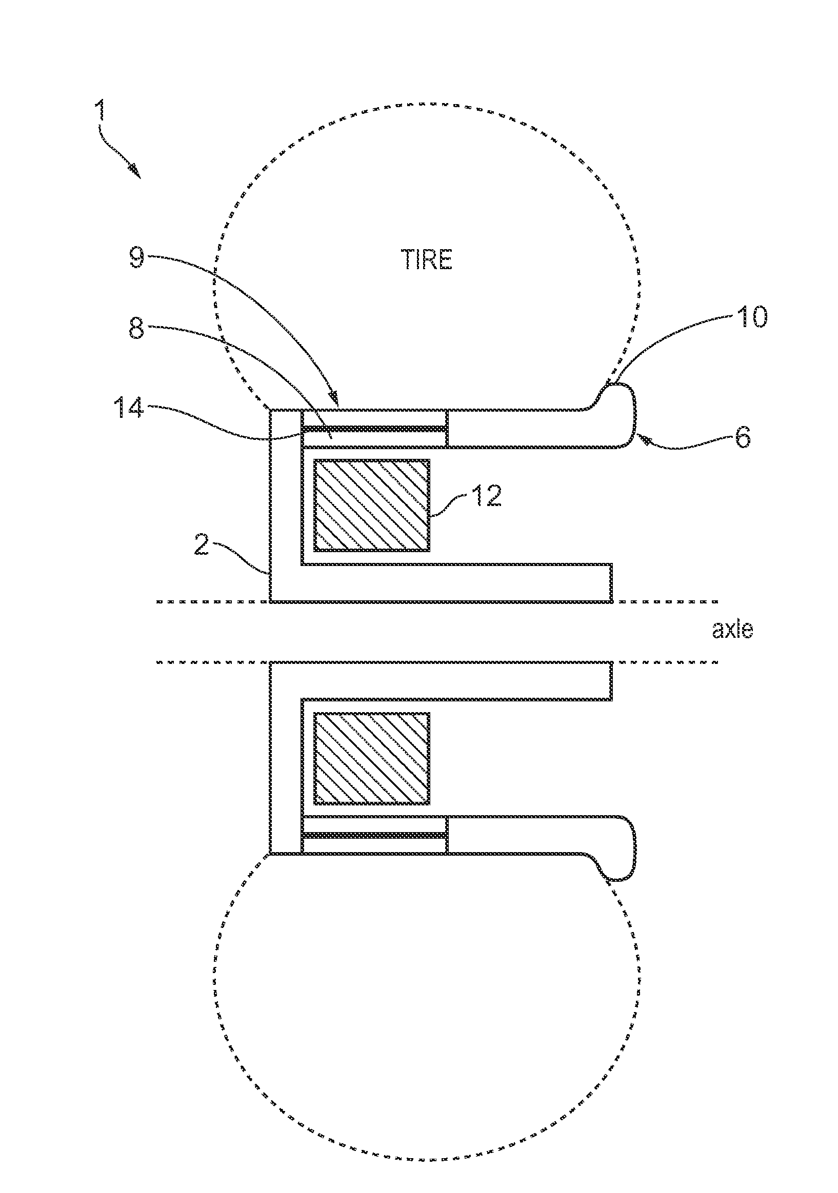
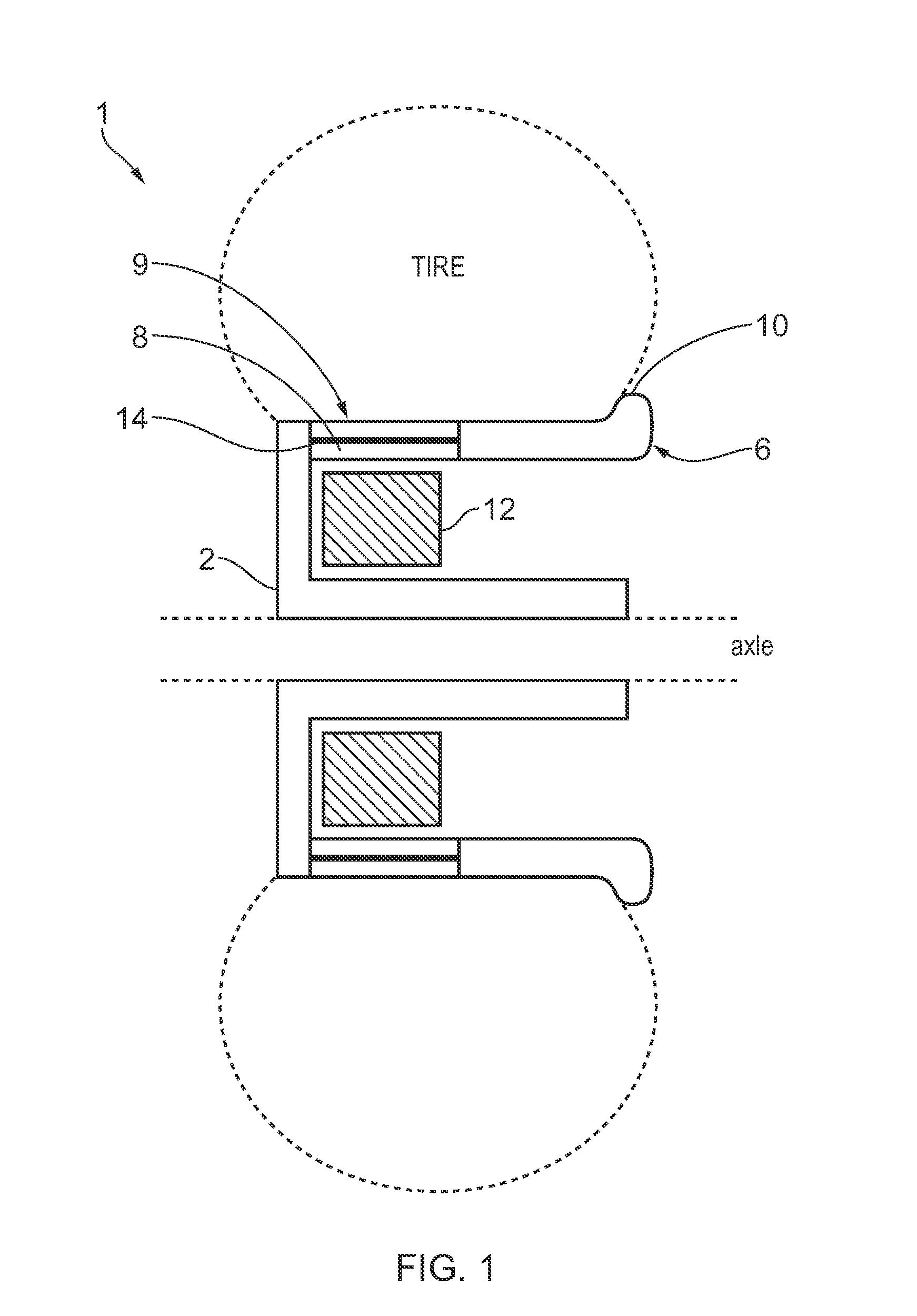
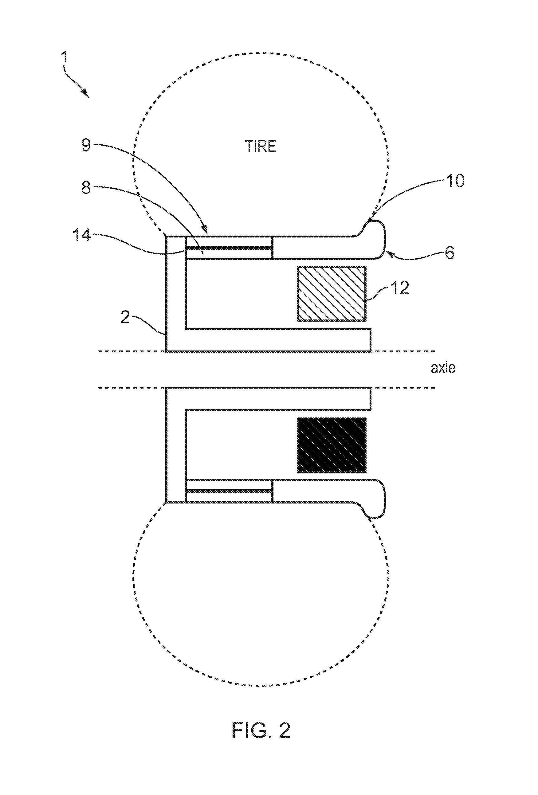
[0040]FIG. 1 shows a cross section of a wheel comprising a brake assembly according to an embodiment of the present invention. The wheel 2 is rotatable about an axle and comprises a rim 6, which extends around the perimeter of the wheel 2. The rim 6 defines the outer edge of a hollow section 4 between the rim 6 and the axle.

[0041]The rim 6 of the wheel 2 is preferably constructed so as to provide a surface upon which to mount a tyre, in accordance with any known method. The rim 6 comprises two portions 9, 10, adjacent to each other along a direction parallel to the rotational axis of the wheel 2, each portion 9, 10 extending around the rim 6 wheel 2. Disposed within the first portion 9 of the rim 6 is an electrically conductive material 8, such as silver or copper. An insulator such as a ceramic or plastic, may also be included in the first portion 9, arranged to prevent heat generated in the conductive material 8 from heating a tyre mounted on the exterior of the rim 6. Heating of ...


PUM


Abstract

A brake assembly for a vehicle comprising a wheel comprising a hollow section and a rim, the rim comprising a first portion comprising an electrically conductive material and a second portion adjacent to the first portion comprising a plurality of a permanent magnets and a stator comprising at least one electromagnetic coil arranged to be located within the hollow section of the wheel, wherein the stator is moveable between a first position in which the at least one electromagnetic coil is inductively coupled to the first portion of the rim when the wheel is rotating relative to the stator, and a second position in which the at least one electromagnetic coil is inductively coupled to the second portion of the rim.

Description

FIELD TO THE INVENTION[0001]The present invention relates to brake assemblies and in particular electromagnetic brake assemblies and methods of operation thereof.BACKGROUND TO THE INVENTION[0002]State of the art brake technologies implemented on aircraft landing gear generally rely exclusively on friction materials to dissipate the kinetic energy associated with motion of an aircraft. In addition, the brake assembly in an aircraft landing wheel occupies substantially all of the wheel cavity, meaning that any electric taxi solution involves mounting a prime mover external to the wheel cavity which takes up valuable space when the landing gear is retracted into the fuselage, and increases wind resistance and noise when the landing gear is deployed.SUMMARY OF THE INVENTION[0003]According to a first aspect of the invention, there is provided a brake assembly for a vehicle comprising a wheel comprising a hollow section and a rim, the rim comprising a first portion comprising an electrica...

Claims


Application Information

Patent Timeline
Patent Type & Authority Applications(United States)
IPC IPC(8): F16D63/00B60T1/10
CPCB60T1/10F16D63/002B60K7/0007B60T8/1703B60L7/24H02K21/222H02K49/043H02K7/12H02K16/02H02K2213/09B60K2007/0053B60K2007/0092F16D61/00B64C25/42B64C25/44B60T13/586B60T13/748F16D49/00F16D2121/20H02P3/04B60L2200/10Y02T10/64B60L7/10B60L7/26H02K7/106
Inventor SCHMIDT, KYLE
Owner MESSIER DOWTY
Why Eureka
Eureka Blog
Learn More