
Polymer electrolyte membrane, a method for fabricating the same, and a membrane-electrode assembly including the same

Active Publication Date: 2015-03-05
KOLON IND INC
View PDF3 Cites 17 Cited by
  • Summary
  • Abstract
  • Description
  • Claims
  • Application Information

AI Technical Summary

Benefits of technology

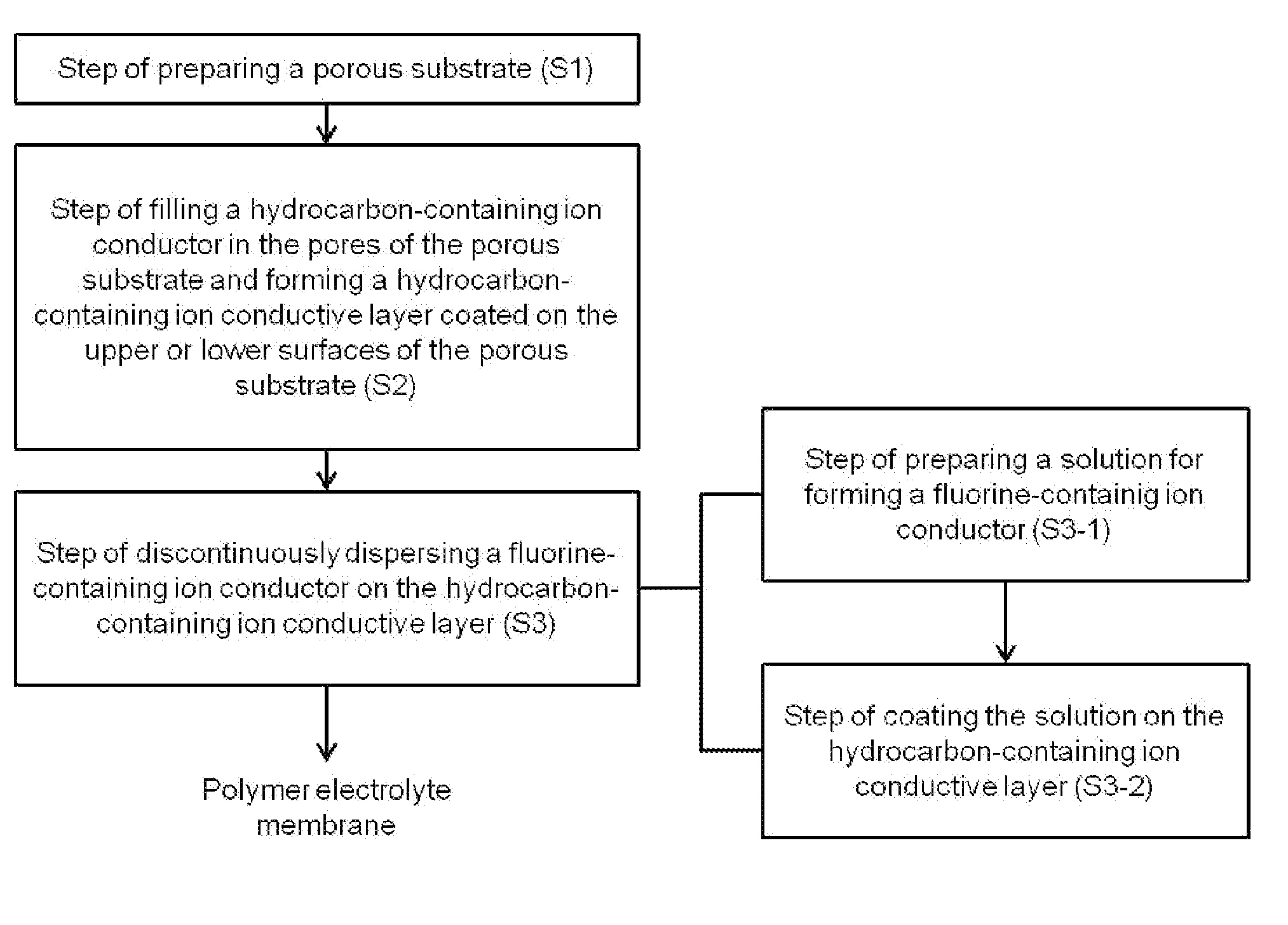
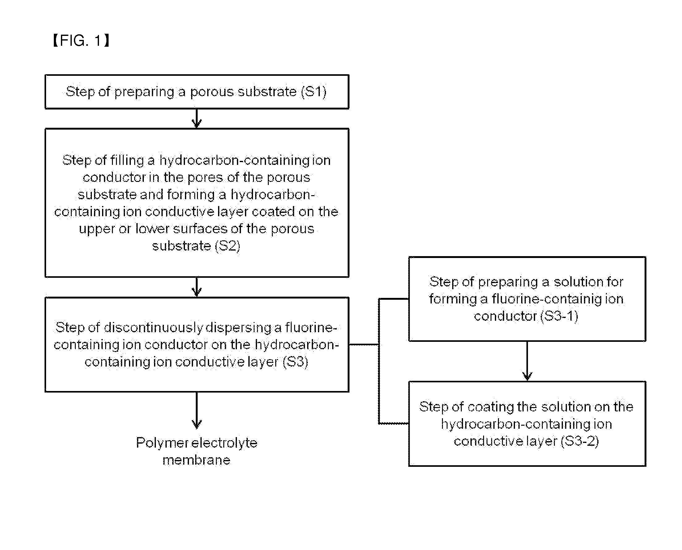
The present invention relates to a new polymer electrolyte membrane that can improve the performance of fuel cells by decreasing interfacial resistance and easily bond to the electrode. The method for producing the membrane can achieve excellent adhesion with minimal amount of fluorine-containing ion conductor. The membrane manufactured by this method has excellent adhesion to the electrode.

Problems solved by technology

However, a fluorine ion conductor has weak mechanical strength, and thus has a problem that when used for a long time, pinholes are generated, and thereby the energy conversion efficiency is decreased.
In order to increase the mechanical strength, there has been an attempt of using a fluorine ion conductor having an increased membrane thickness; however, in this case, there is a problem that the ohmic loss is increased, and the use of expensive materials increases, so that the economic efficiency is low.
However, since a Teflon resin has very poor adhesiveness, there are limitations on the selection of the ion conductor, and in the case of products produced by applying fluorine ion conductors, the products have a disadvantage that the fuel crossover phenomenon occurs conspicuously as compared with hydrocarbon-based ion conductors.
Furthermore, because not only fluorine ion conductors but also porous Teflon resins are highly expensive, there still is a demand for the development of a new inexpensive material for the mass production of fuel cells.
However, the electrode has a poor adhesion with the hydrocarbon-containing ion conductor, the hydrocarbon-containing ion conductor being researched recently.
However, the hydrocarbon-containing ion conductor is not efficient for the decal process due to their surface property.

Method used


Image

  • Polymer electrolyte membrane, a method for fabricating the same, and a membrane-electrode assembly including the same
  • Polymer electrolyte membrane, a method for fabricating the same, and a membrane-electrode assembly including the same

Examples


preparation example

Preparation of Polymer Electrolyte Membrane and Membrane-Electrode Assembly

example 1

[0099]A S-PEEK (sulfonated polyether ether ketone) was dissolved in N-methyl-2-pyrrolidone (NMP), and thus a 10 wt % ion conductor solution was prepared. The ion conductor solution was coated on the glass substrate. The coated layer was dried for 24 hours at 50° C. Then, the coated layer was separated from the glass substrate, thereby a hydrocarbon-containing ion conductive layer having a thickness of 20 μm was formed.

[0100]A solution for forming the fluorine-containing ion conductor was prepared by adding DMF of 5% into the IPA dispersion containing 10% of a Nafion. The fluorine-containing ion conductor was formed by spraying the solution for forming the fluorine-containing ion conductor on the surface of the hydrocarbon-containing ion conducting layer, and then drying at 80° C. for 10 hours.

[0101]On the other hand, an electrode was prepared by coating an electrode slurry containing a Nafion binder on a PI film, and was cut out into the size of 5×5 cm2. The electrode thus produced ...

example 2

[0102]A membrane-electrode assembly was produced in the same manner as in Example 1, except that a fiber-shaped fluorine-containing ion conductor was discontinuously dispersed by electrospinning the solution for forming the fluorine-containing ion conductor on the surface of the hydrocarbon-containing ion conductive layer.


PUM

PropertyMeasurementUnit
Fractionaaaaaaaaaa
Diameteraaaaaaaaaa
Diameteraaaaaaaaaa

Abstract

Disclosed are a polymer electrolyte membrane, a method for manufacturing the same and a membrane-electrode assembly comprising the same, the polymer electrolyte membrane includes a hydrocarbon-containing ion conductive layer; and a fluorine-containing ion conductor discontinuously dispersed on the hydrocarbon-containing ion conductive layer.

Description

TECHNICAL FIELD[0001]The present invention relates to a polymer electrolyte membrane, a method for manufacturing the same and a membrane-electrode assembly comprising the same. More particularly, the present invention relates to a polymer electrolyte membrane which has an excellent adhesion to an electrode, accordingly can improve the performance of a fuel cell by decreasing the interfacial resistance, and can easily bond to the electrode by transferring with improved efficiency.BACKGROUND ART[0002]Fuel cells are cells that directly convert the chemical energy generated by oxidation of a fuel to electrical energy, and attention is being paid to the fuel cells as a next-generation energy source due to their environment-friendly features of high energy conversion efficiency and reduced contaminant discharge.[0003]A fuel cell generally has a structure in which an anode and a cathode are formed, with an electrolyte membrane interposed therebetween, and such a structure is called a membr...

Claims


Application Information

Patent Timeline
IPC IPC(8): H01M8/10
CPCH01M8/1067H01M8/1053H01M2300/0082H01M2008/1095H01M8/1081H01M8/102H01M8/106H01M8/1069H01M8/1048Y02P70/50Y02E60/50
Inventor LEE, MOO SEOKSHIN, YONG CHEOLKIM, NA YOUNGLEE, DONG HOON
Owner KOLON IND INC
Learn More