
Pemfc electrode structuring

Inactive Publication Date: 2014-05-08
COMMISSARIAT A LENERGIE ATOMIQUE ET AUX ENERGIES ALTERNATIVES
View PDF0 Cites 4 Cited by
  • Summary
  • Abstract
  • Description
  • Claims
  • Application Information

AI Technical Summary

Benefits of technology

This patent text relates to a fuel cell comprising a catalytic layer, an electrolytic membrane, and a gas diffusion layer that have improved performance compared to a fuel cell without these structures. The text also mentions that using an ink containing circular structures at a certain concentration and with a certain bead size can enhance the performance of a fuel cell. Additionally, the text explains that alcohol can improve the wetting of the ink and the accuracy of drop positioning on the printed surface, which can lead to better fuel cell performance.

Problems solved by technology

Typically, such structures do not have a uniform thickness.

Method used


Image

  • Pemfc electrode structuring
  • Pemfc electrode structuring
  • Pemfc electrode structuring

Examples


Embodiment Construction

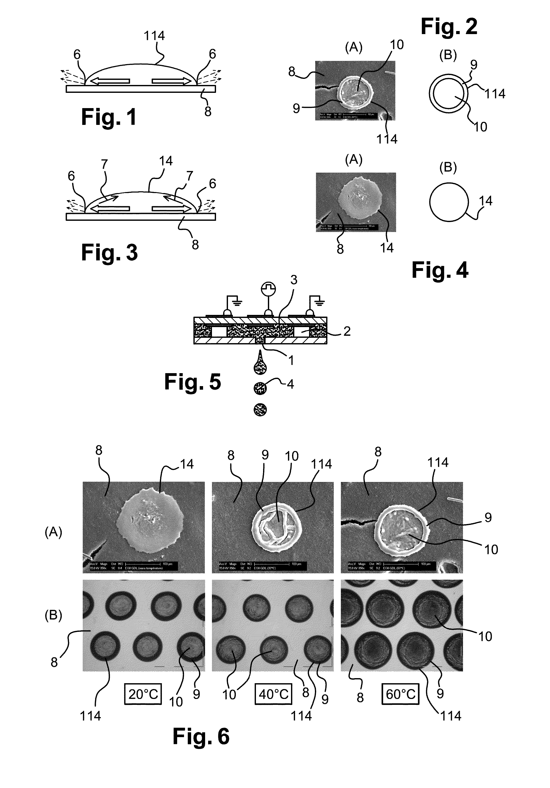
[0088]To form fuel cell electrodes having an improved performance and a low production cost, the invention has shown the advantage of promoting the coffee ring effect to structure said electrodes and an ink adapted to the forming thereof.

[0089]1 / Ink Definition:

[0090]The ink used to form the electrode which is the object of the invention should be compatible with drop-on-demand or DOD-type inkjet printers. FIG. 5 illustrates a printing head of such an inkjet printer. The printing head in particular comprises a nozzle 1, through which the ink comes out in the form of drops 4. The drop size (or diameter) thus depends, in particular, on the nozzle opening. The expelling of a drop 4 may be caused in different ways. In FIG. 5, the application of an electric signal to piezoelectric elements 2 causes a slight contraction of the reservoir containing ink 3 in the printing head. There also exist other technologies enabling to accurately control the expelling of a drop by the nozzle of an inkje...


PUM

PropertyMeasurementUnit
Temperatureaaaaaaaaaa
Fractionaaaaaaaaaa
Diameteraaaaaaaaaa

Abstract

A method of deposition, by drop-on-demand inkjet printing, of the catalytic layer of a fuel cell comprising the deposition, on a printing surface, of an ink generating substantially circular structures comprising a bead at their periphery.

Description

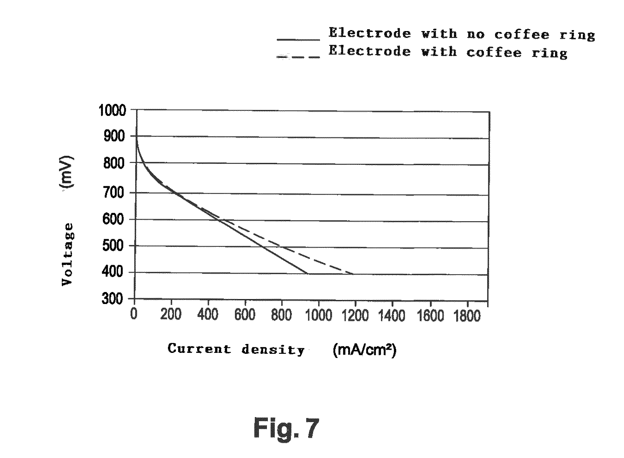
FIELD OF THE INVENTION[0001]The present invention relates to the manufacturing of structured electrodes, by the inkjet printing technique, and more specifically by DOD (“Drop On Demand”) or microdispersing. According to the invention, structured electrodes appear in the form of substantially circular structures comprising a bead at their periphery, which result from a so-called “coffee ring” phenomenon.[0002]The invention especially applies in the field of PEMFCs (“Polymer Electrolyte Membrane Fuel Cells”). Indeed, unexpectedly, a cell provided with such electrodes has an improved performance.BACKGROUND[0003]Much research is carried out in the field of fuel cells to improve the performance and to decreasing production cost for such electrochemical devices. In particular, fuel cells are considered as a promising alternative to power sources based on the use of hydrocarbons, which are finite resources and generate an undesirable pollution by their combustion.[0004]Fuel cells have an o...

Claims


Application Information

Patent Timeline
IPC IPC(8): H01M4/88H01M8/10H01M4/86
CPCH01M4/8832H01M8/1002H01M4/8626H01M4/8807H01M4/881H01M8/1007Y02E60/50Y02P70/50C23C26/00H01M4/88
Inventor VINCENT, REMIMERCIER, ANNE-GAELLE
Owner COMMISSARIAT A LENERGIE ATOMIQUE ET AUX ENERGIES ALTERNATIVES
Learn More