
Method for making a current-perpendicular-to-the-plane (CPP) magnetoresistive sensor containing a ferromagnetic alloy requiring post-deposition annealing

a technology of magnetoresistive sensor and ferromagnetic alloy, which is applied in the field of current perpendicular to the plane (cpp) magnetoresistive sensor, can solve the problems of reducing the pinning strength, altering the desired composition and only marginal improvement of the cofeb interface layer, so as to improve the microstructure of the heusler alloy

Inactive Publication Date: 2013-09-12
WESTERN DIGITAL TECH INC
View PDF5 Cites 38 Cited by
  • Summary
  • Abstract
  • Description
  • Claims
  • Application Information

AI Technical Summary

Benefits of technology

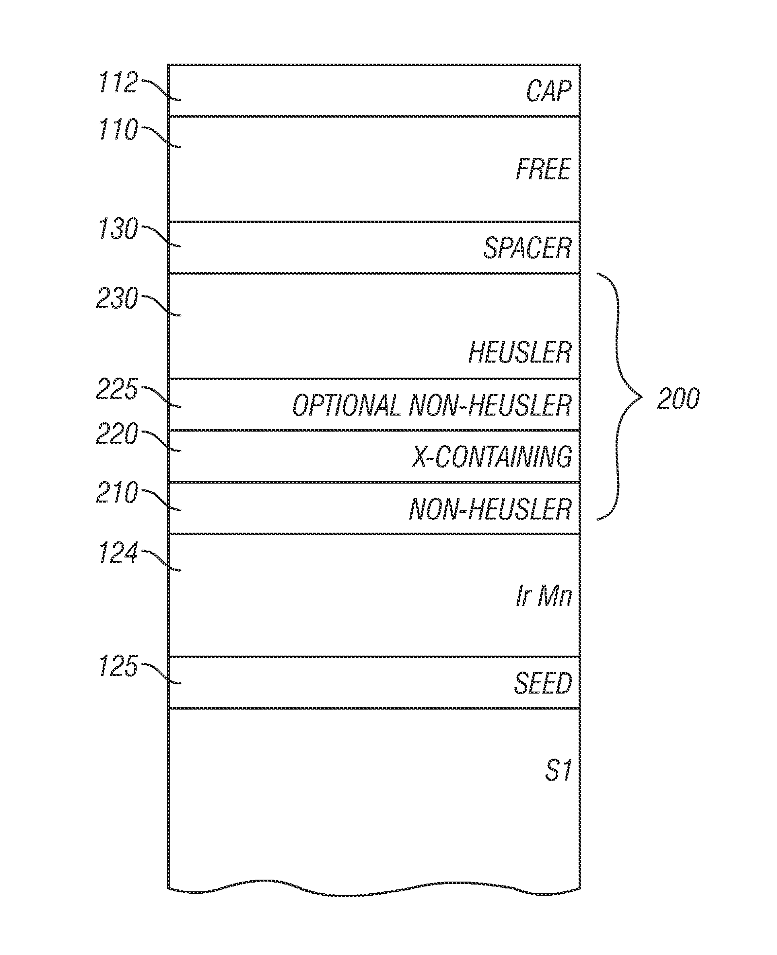
The invention is about a way to make a sensor called CPP-GMR, which uses a special layer made of a material called Heusler alloy. This layer is pinned by another material called an antiferromagnetic pinning layer. A layer of a crystalline material called a non-Heusler alloy ferromagnetic material is deposited on top of the antiferromagnetic pinning layer, and a layer of an amorphous ferromagnetic alloy made of cobalt, iron, and other elements is deposited on top of the non-Heusler alloy layer. The amorphous layer contains enough boron to make it almost completely mixed together with the alloy. Annealing is then performed to improve the quality of the layers. The remaining layers are deposited and annealed. This process results in a sensor that can detect small magnetic fields.

Problems solved by technology

However, at high annealing temperatures the Mn in the antiferromagnetic pinning layer diffuses into other layers in the sensor stack, which reduces the pinning strength and alters the desired composition of the Heusler alloy.
This results in degraded sensor performance.
However, after post-deposition annealing the sensor with the CoFeB interface layer exhibits only marginal improvement in magnetoresistance.

Method used


Image

  • Method for making a current-perpendicular-to-the-plane (CPP) magnetoresistive sensor containing a ferromagnetic alloy requiring post-deposition annealing
  • Method for making a current-perpendicular-to-the-plane (CPP) magnetoresistive sensor containing a ferromagnetic alloy requiring post-deposition annealing
  • Method for making a current-perpendicular-to-the-plane (CPP) magnetoresistive sensor containing a ferromagnetic alloy requiring post-deposition annealing

Examples


Embodiment Construction

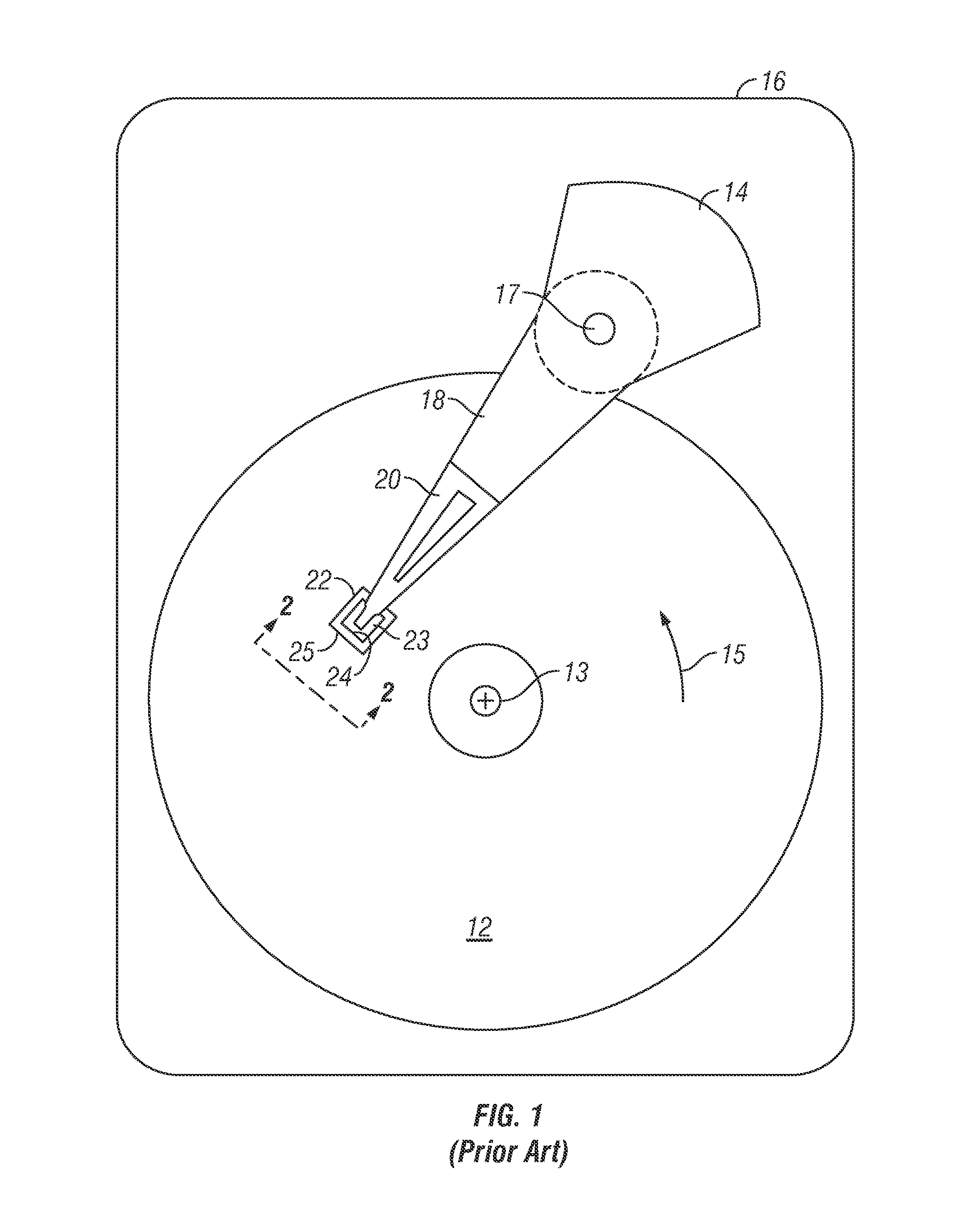
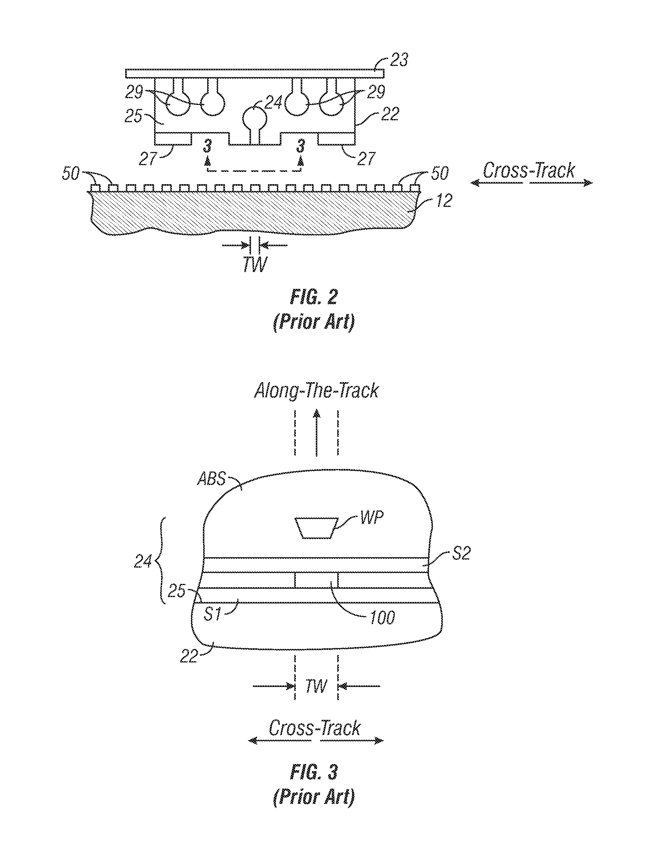
[0018]The CPP magnetoresistive (MR) sensor made according to this invention has application for use in a magnetic recording disk drive, the operation of which will be briefly described with reference to FIGS. 1-3. FIG. 1 is a block diagram of a conventional magnetic recording hard disk drive. The disk drive includes a magnetic recording disk 12 and a rotary voice coil motor (VCM) actuator 14 supported on a disk drive housing or base 16. The disk 12 has a center of rotation 13 and is rotated in direction 15 by a spindle motor (not shown) mounted to base 16. The actuator 14 pivots about axis 17 and includes a rigid actuator arm 18. A generally flexible suspension 20 includes a flexure element 23 and is attached to the end of arm 18. A head carrier or air-bearing slider 22 is attached to the flexure 23. A magnetic recording read / write head 24 is formed on the trailing surface 25 of slider 22. The flexure 23 and suspension 20 enable the slider to “pitch” and “roll” on an air-bearing gen...


PUM

PropertyMeasurementUnit
temperatureaaaaaaaaaa

Abstract

A method for making a current-perpendicular-to the-plane giant magnetoresistance (CPP-GMR) sensor with a Heusler alloy pinned layer on the sensor's Mn-containing antiferromagnetic pinning layer uses two annealing steps. A layer of a crystalline non-Heusler alloy ferromagnetic material, like Co or CoFe, is deposited on the antiferromagnetic pinning layer and a layer of an amorphous X-containing ferromagnetic alloy, like a CoFeBTa layer, is deposited on the Co or CoFe crystalline layer. After a first in-situ annealing of the amorphous X-containing ferromagnetic alloy, the Heusler alloy pinned layer is deposited on the amorphous X-containing ferromagnetic layer and a second high-temperature annealing step is performed to improve the microstructure of the Heusler alloy pinned layer.

Description

BACKGROUND OF THE INVENTION[0001]1. Field of the Invention[0002]The invention relates generally to a current-perpendicular-to-the-plane (CPP) magnetoresistive sensor that operates with the sense current directed perpendicularly to the planes of the layers making up the sensor stack, and more particularly to an improved method for making a CPP sensor that contains a ferromagnetic alloy, like a Heusler alloy, that requires high-temperature post-deposition annealing.[0003]2. Background of the Invention[0004]One type of conventional magnetoresistive (MR) sensor used as the read head in magnetic recording disk drives is a “spin-valve” sensor based on the giant magnetoresistance (GMR) effect. A GMR spin-valve sensor has a stack of layers that includes two ferromagnetic layers separated by a nonmagnetic electrically conductive spacer layer, which is typically formed of Cu or Ag. One ferromagnetic layer, typically called the “reference” layer, has its magnetization direction fixed, such as ...

Claims


Application Information

Patent Timeline
Patent Type & Authority Applications(United States)
IPC IPC(8): G11B5/127
CPCG11B5/3163G11B5/3906G01R33/093H01L43/08H01F41/303H01F10/1936H01F10/3268H01F10/3295H01L43/12H10N50/10H10N50/01
Inventor CAREY, MATTHEW J.CHANDRASHEKARIAIH, SHEKAR B.CHILDRESS, JEFFREY R.CHOI, YOUNG-SUKREAD, JOHN CREIGHTON
Owner WESTERN DIGITAL TECH INC
Learn More