
Electrode having enzyme crystals immobilized thereon, method for producing electrode having enzyme crystals immobilized thereon, and biological fuel cell and biosensor provided with electrode having enzyme crystals immobilized thereon

a technology of enzyme crystals and electrodes, which is applied in the direction of immobilized enzymes, diaphragms, oxidoreductases, etc., can solve the problems of unstable enzyme on the electrode, inability to obtain the amount of enzyme binding, and inability to achieve electric current, etc., to achieve excellent electrode performance, even smoother manner, excellent electrode performance

Active Publication Date: 2013-08-29
AISIN SEIKI KK +1
View PDF0 Cites 9 Cited by
  • Summary
  • Abstract
  • Description
  • Claims
  • Application Information

AI Technical Summary

Benefits of technology

The present invention provides a method for immobilizing an enzyme onto the surface of an electroconductive base material with a uniform, high density, and constantly aligned orientation, resulting in an electrode with smooth catalytic function. The resulting electrode exhibits excellent electrode performance, making it possible to generate high-capacity and high-output power, and to produce a highly accurate biosensor with excellent durability. Overall, the invention is advantageous for various applications in biosensors and bioenergy devices.

Problems solved by technology

Biological fuel cells, which use a biomass resource, have recently been proposed as being the next generation of energy, due to the high energy efficiency and low environmental impact thereof.
For this reason, a problem has emerged in that the enzyme on the electrode has become unstable and an electric current value that is consistent with the amount of enzyme binding cannot be obtained.
Another problem has emerged in that the types of enzyme that can be applied have been limited, the applications of the electrode disclosed in Patent Document 2 being limited to membrane-bound enzymes and the electrode disclosed in Patent Document 3 not being applicable to enzymes having a hydrophilic surface, and so forth.
There are limitations, however, to the use of a highly concentrated solution in a case where the enzyme is to be immobilized onto the electroconductive base material in a solution state.
However, when the enzyme is highly concentrated, there are incidental interactions between the hydrophobic portions when the enzyme molecules come into close proximity to each other; aggregation and precipitation take place as a result, leading to denaturing of the enzyme and exposure of the enzyme in an unstable state.
This causes electron transfer on the electrode to no longer proceed in a smooth manner, and a problem emerges in that the resulting enzyme electrode will have poor electrode performance.
Factors whereby an amount of electric current that is consistent with the amount of enzyme binding might not be obtained also include the fact that there is inadequate optimization of the directionality (orientation) of the enzyme binding on the electrode.
When immobilization is carried out in a solution state, therefore, the enzyme binds to the electroconductive base material with a random directionality, and this leads to a decrease in output and the like.
For this reason, the ability to control the orientation of the enzyme on the electrode has been a technical problem requiring improvement, from the point of view of electrode performance.
Furthermore, in immobilization in a solution state, immobilizing the enzyme onto the electrode while a constant dispersibility is upheld is difficult, and for this reason a problem has emerged in that the enzyme readily dissociates from the electrode within the electrolyte solution, and there is a decline in the electric current value when the oxidation current is measured.

Method used


Image

  • Electrode having enzyme crystals immobilized thereon, method for producing electrode having enzyme crystals immobilized thereon, and biological fuel cell and biosensor provided with electrode having enzyme crystals immobilized thereon
  • Electrode having enzyme crystals immobilized thereon, method for producing electrode having enzyme crystals immobilized thereon, and biological fuel cell and biosensor provided with electrode having enzyme crystals immobilized thereon
  • Electrode having enzyme crystals immobilized thereon, method for producing electrode having enzyme crystals immobilized thereon, and biological fuel cell and biosensor provided with electrode having enzyme crystals immobilized thereon

Examples


example 1

Construction of an Enzyme Expression System, Enzyme Synthesis Through an E. Coli Protein Synthesis System, and Protein Purification

[0164]In order to acquire a high-purity enzyme in the process of crystallization, a genetic engineering technique was used to produce an enzyme as a recombinant protein, which was then purified through a combination of a variety of different forms of chromatography. In particular for the process of crystallization, large quantities of purified enzyme are needed for screening to optimize the crystallization conditions.

[0165]Step 1: Construction of an Expression Vector for Glucose Dehydrogenase from Acinetobacter

[0166]A glucose dehydrogenase gene was acquired by amplification from Acinetobacter calcoaceticus purchased from the National Institute of Technology and Evaluation (NITE), and the sequence thereof served as the basis for rewriting of the sequence so that the amino acids would be the same as the amino acid sequence of Acinetobacter calcoaceticus g...

example 2

Purity Assay of the Purified Enzyme

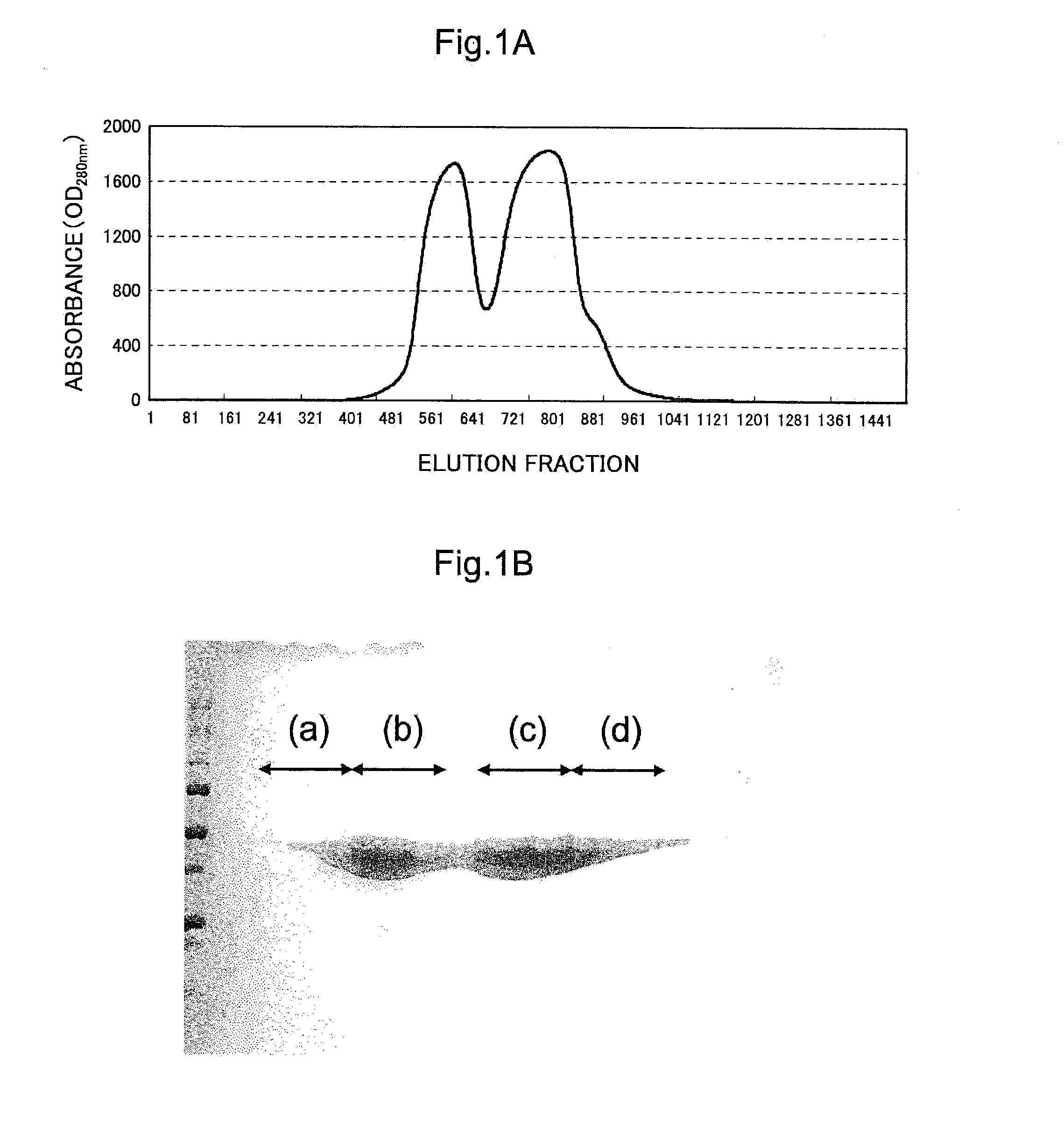
[0185]In the present example, the question of whether the purified enzyme acquired in example 1 was the high-purity enzyme needed for crystallization was checked. More specifically, this check was carried out by quantifying the enzyme present in the protein solution that was purified by affinity chromatography in example 1, as well as the enzyme present in the protein solution that was purified through the combination of affinity chromatography and ion exchange chromatography. A fraction equivalent to the region in segment (c) in FIG. 1B was used as the sample purified by the combination of affinity chromatography and ion exchange chromatography.

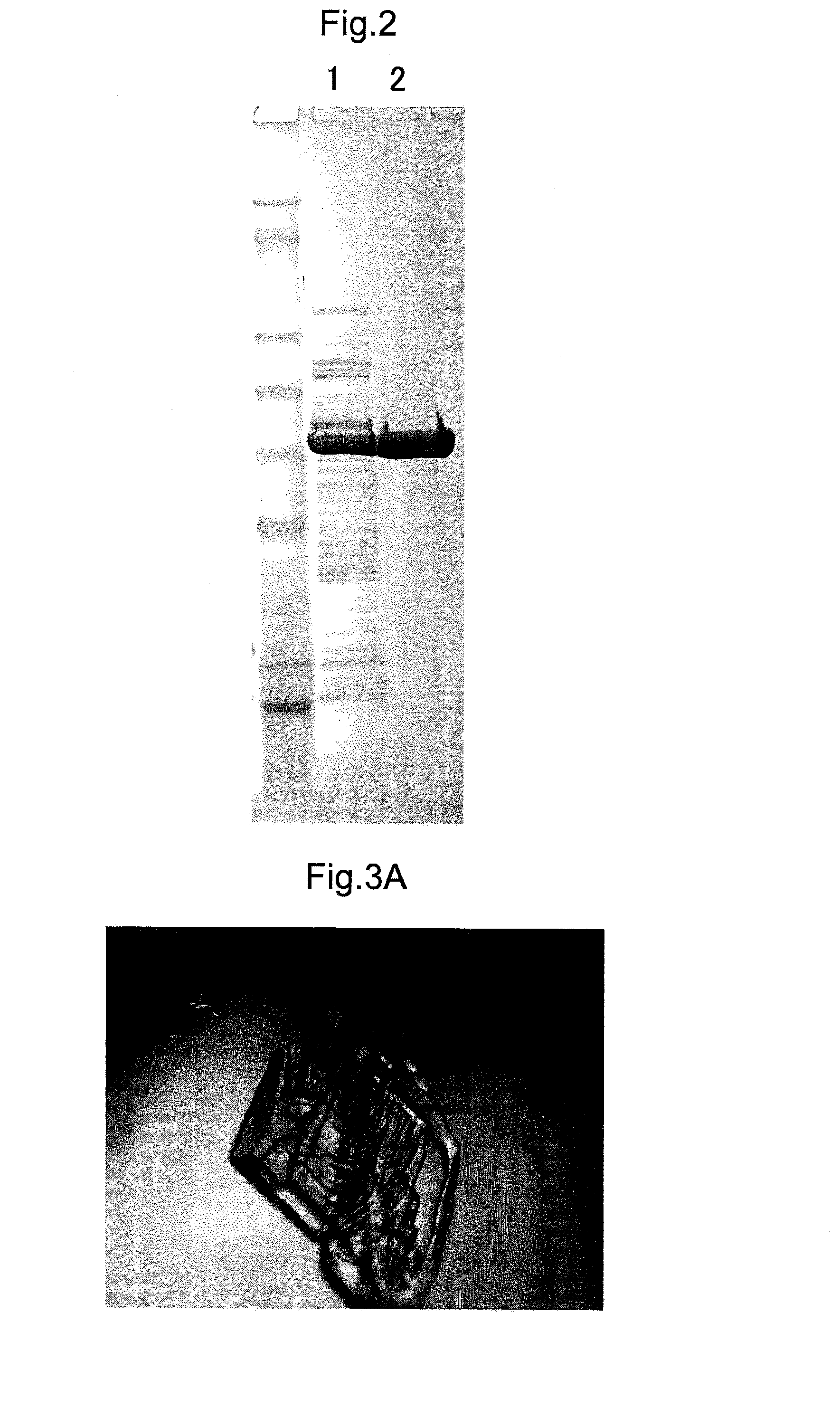
[0186]First, the eluted protein was confirmed in advance of the quantification. The protein solutions following the purifications described above underwent SDS-PAGE electrophoresis, which was followed by staining with the protein staining agent Flamingo Fluorescent Gel Stain (Bio-Rad), and band visualizatio...

example 3

Screening for Enzyme Crystallization Conditions, and Crystallization of the Enzyme

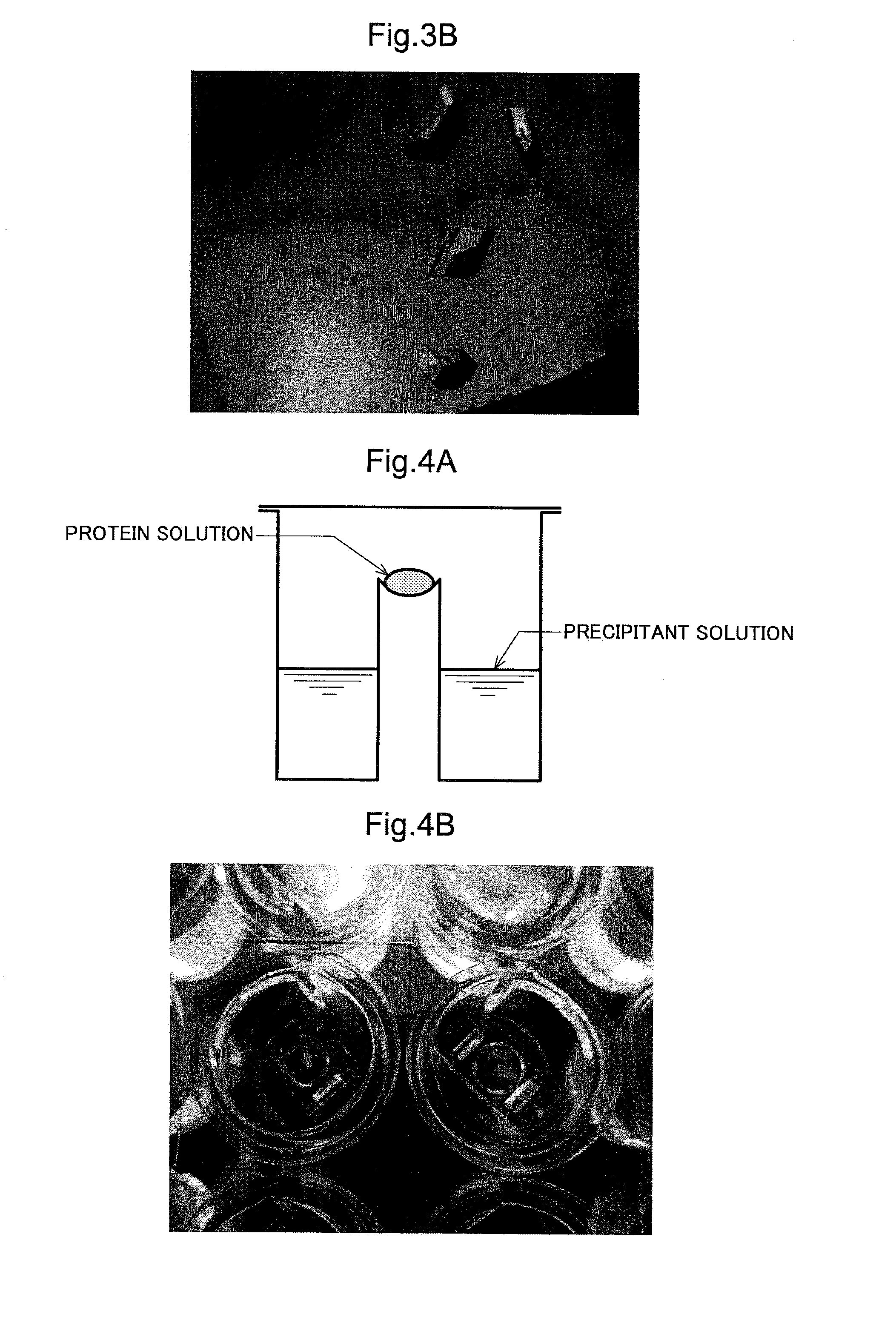
[0191]In the present example, an investigation for the purpose of crystallizing the enzyme purified in example 1 was conducted. A fraction, equivalent to the region in segment (c) in FIG. 1B, of the enzyme acquired in example 1 was used as the target of crystallization, and the crystallization was carried out by the vapor diffusion method. The reason for which segment (c) in FIG. 1B was selected is that when the stability of the enzyme precipitant solution in the buffer solution composition (50 mM Tris-HCl (pH 9.3), 120 mM NaCl, 3 mM CaCl2) was compared on the basis of fractions equivalent to the regions in segments (b) and (c) in FIG. 1B, it was demonstrated that segment (b) had slightly lower stability in storage of several days or longer. For this reason, segment (c), which was preferable also on the basis of the quality and quantity of the enzyme, was selected as being intended for crystallization....


PUM

PropertyMeasurementUnit
concentrationaaaaaaaaaa

Abstract

An objective of the present invention is to establish a technique for making it possible to immobilize an enzyme on an electrically conductive base material in a uniformly, high density, and constantly aligned orientation, for the purpose of constructing an enzyme electrode having improved electrode performance. An electrode having enzyme crystals immobilized thereon, the electrode being provided with an electrically conductive base material that can be connected to an external circuit and enzyme crystals that serve as an electrode catalyst, wherein the enzyme crystals are immobilized on the electrically conducive base material; a method for producing an electrode having enzyme crystals immobilized thereon; and a biological fuel cell and a biosensor which are provided with an electrode having enzyme crystals immobilized thereon.

Description

TECHNICAL FIELD[0001]The present invention relates to an electrode having enzyme crystals immobilized thereon, a method for producing an electrode having enzyme crystals immobilized thereon, and a biological fuel cell and biosensor provided with an electrode having enzyme crystals immobilized thereon. More specifically, the present invention relates to an electrode having enzyme crystals immobilized thereon, where enzyme crystals are immobilized on the surface of an electroconductive base material, as well as to a method for producing an electrode having enzyme crystals immobilized thereon and a biological fuel cell and biosensor provided with the electrode having enzyme crystals immobilized thereon.BACKGROUND ART[0002]Biological fuel cells, which use a biomass resource, have recently been proposed as being the next generation of energy, due to the high energy efficiency and low environmental impact thereof. Organisms, including microorganisms, generate ATP and other chemical energy...

Claims


Application Information

Patent Timeline
Patent Type & Authority Applications(United States)
IPC IPC(8): C12N11/06H01M8/16H01M8/00C25B11/04
CPCC12N9/0006C12N9/0061C12Q1/001C12Y101/05002H01M4/9008H01M4/90Y02E60/527C12N11/14C12N11/06C25B11/0442H01M8/00H01M8/16C25B11/073Y02E60/50Y02P70/50
Inventor SHIGEMORI, YASUSHINAKAOKI, YUICHIROMIKAWA, TSUTOMU
Owner AISIN SEIKI KK
Learn More