
Laminated electronic component and manufacturing method thereof

Inactive Publication Date: 2013-08-22
TAIYO YUDEN KK
View PDF7 Cites 2 Cited by
  • Summary
  • Abstract
  • Description
  • Claims
  • Application Information

AI Technical Summary

Benefits of technology

The patent text discusses a method for improving the accuracy and reliability of laminated electronic components. The invention provides a method for adding an ESR function to these components using a high-resistance layer made of cermet film. The cermet film can be produced using a sputtering method, allowing for precise control of its thickness and ensuring accurate ESR performance and reliable moisture resistance. The method also allows for resistance control over a wide range and simplifies the process for manufacturing highly reliable components. Additionally, the method involves forming a cermet layer directly on the internal electrodes, resulting in a highly reliable component with simple steps. Overall, the invention provides a solution for enhancing the performance and reliability of laminated electronic components.

Problems solved by technology

As a result, a circuit in which such laminated ceramic capacitor is mounted causes the problem that the temperature stability of the circuit becomes lower.
In addition, producing a laminated ceramic capacitor using the method described in Patent Literature 2 gives rise to the problem of lower moisture resistance because the high-resistance layer uses resin.
In addition, the laminated ceramic capacitors described in Patent Literature 3 and Patent Literature 4 are such that their base electrodes formed by baking have a significant surface irregularity.
This gives rise to the problem that strict control of the ESR becomes difficult.

Method used


Image

  • Laminated electronic component and manufacturing method thereof
  • Laminated electronic component and manufacturing method thereof
  • Laminated electronic component and manufacturing method thereof

Examples


Embodiment Construction

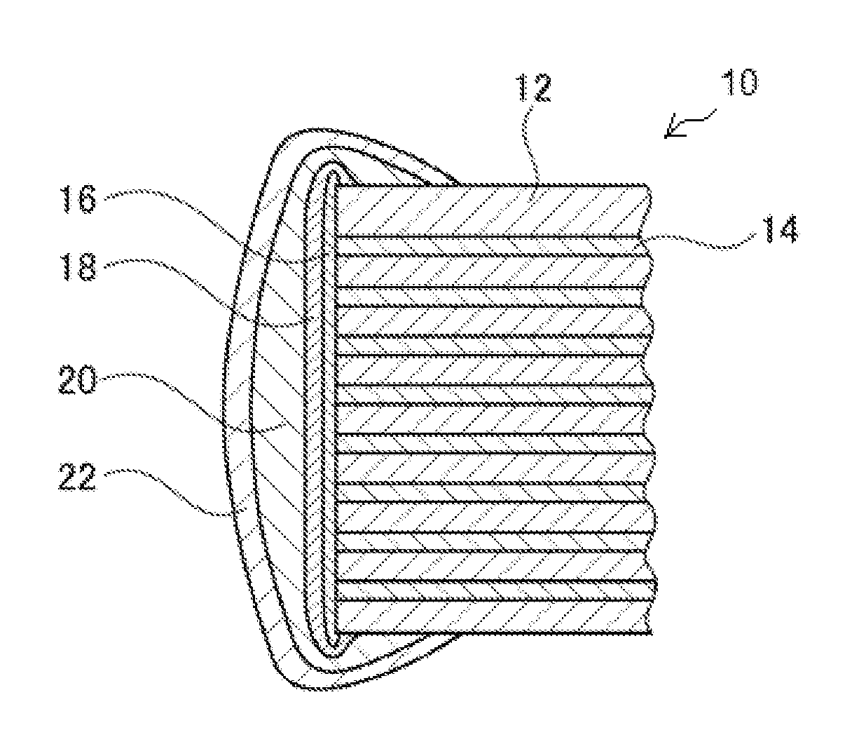
[0041]An embodiment of the laminated electronic component proposed by the present invention is explained by referring to the drawings. FIG. 1 is a cross-section view explaining an embodiment in which a laminated electronic component 10 pertaining to the present invention is applied as a laminated ceramic capacitor offering favorable temperature characteristics of capacitance as well as B characteristics.

[0042]The laminated electronic component 10 is structured in such a way that a dielectric layer 12 whose main component is barium titanate are alternately layered with internal electrodes 14.

[0043]For the dielectric layer 12 of the laminated electronic component 10, a composition powder of composite materials, primarily barium titanate, can be mixed with organic binder and solvent and a mixture is shaped into a sheet of approx. 5 μm in thickness using the doctor blade method, and the obtained sheet can be used. For the internal electrodes 14, the same sheet used for the dielectric la...


PUM

PropertyMeasurementUnit
Thicknessaaaaaaaaaa
Electrical resistanceaaaaaaaaaa
Temperature coefficient of refractive indexaaaaaaaaaa

Abstract

A laminated electronic component includes a laminate formed by alternately layering multiple internal electrodes and dielectrics, with the internal electrodes alternately exposed on the respective end faces of the laminate and two sets of external electrodes formed on them, wherein the external electrodes have a cermet layer that is film-formed by the sputtering method. Stable ESR (Equivalent Series Resistance) can be set over a wide range by changing the composition and film thickness of the cermet layer. In addition, ESR can be added that ensures low temperature coefficient and resistance to the impact of humidity change.

Description

BACKGROUND[0001]1. Field of the Invention[0002]The present invention relates to a laminated electronic component such as laminated ceramic capacitor, and particularly to a laminated electronic component whose ESR (Equivalent Series Resistance) can be adjusted, as well as a manufacturing method of said laminated electronic component.[0003]2. Description of the Related Art[0004]Laminated ceramic capacitors are structured by a ceramic laminate of roughly solid rectangular shape in which multiple internal electrodes and dielectric ceramics are alternately layered, wherein the layers of internal electrodes are alternately exposed on the different end faces of the ceramic laminate and two sets of external electrodes are formed on them. In general, the external electrodes are constituted by multiple conductive layers, such as base metal layers connected to the internal electrodes, plated metal layers designed to protect the base metal layers and improve the solder wettability, and the like...

Claims


Application Information

Patent Timeline
IPC IPC(8): H01G4/30
CPCH01G4/30H01G4/2325H01G4/12
Inventor SAITO, KENJI
Owner TAIYO YUDEN KK
Learn More