
Flexible metal laminate containing fluoropolymer

a metal laminate and fluoropolymer technology, applied in the direction of high frequency circuit adaptation, instruments, transportation and packaging, etc., can solve the problems of low heat resistance, low compatibility with a pcb manufacturing process using the existing polyimide, and low tg (glass transition temperature), so as to improve the adhesion of a metal layer, inhibit the precipitation of fluoropolymer on the surface, and improve the effect of heat resistan

Active Publication Date: 2013-03-14
GUANGDONG SHENGYI SCI TECH
View PDF5 Cites 21 Cited by
  • Summary
  • Abstract
  • Description
  • Claims
  • Application Information

AI Technical Summary

Benefits of technology

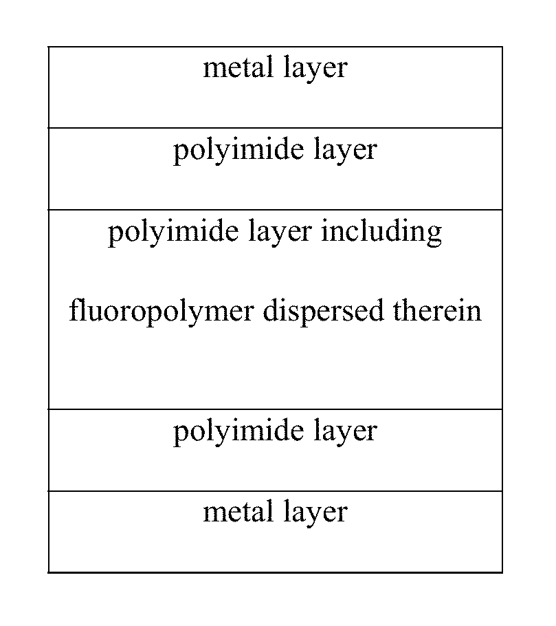
The flexible metal laminate described in this patent has layers of polyimide with fluoropolymer dispersed in it, which improves adhesion to metal and prevents the fluoropolymer from causing electrical arcing. The polyimide layers also have improved heat resistance and thermal expansion. The laminate has low dielectric constant, low dielectric loss, and low water absorption, but also has the insulation properties of existing polyimide materials, such as high heat resistance, high chemical resistance, high flexibility, and dimensional stability.

Problems solved by technology

However, dielectric constant of LCP (Dk=2.9) is less excellent than dielectric constant of polyimide (Dk=3.2), it has too low heat resistance, and it has low compatibility with a PCB manufacturing process using the existing polyimide.
However, it has limitation that it directly uses polyimide having high coefficient of thermal expansion and low Tg (glass transition temperature).
However, it has problems in that adhesion to a coverlay or adhesion to prepreg decreases.
And, since CTE values in the Examples of the above patent are too large, it has a limitation for use as a flexible metal laminate.
Moreover, since fluoropolymer is exposed on the surface, the fluoropolymer is dissolved during a high temperature storage process, thus causing a risk of delamination of copper foil circuit from an insulator.

Method used


Image

  • Flexible metal laminate containing fluoropolymer
  • Flexible metal laminate containing fluoropolymer
  • Flexible metal laminate containing fluoropolymer

Examples


example 1

Preparation of Polyamic Acid Varnish Including Fluoropolymer Powder Dispersed Therein (1)

[0076]After charging nitrogen into a 1 L PE bottle, 300 g of DMAc, 57 g of PTFE powder (average particle diameter 0.1 to 2 um), 5.7 g of a polyester-based dispersant of polycaprolactone diol (Mn=2000), and 200 g of ball mill were introduced, and the mixture was agitated in a high speed ball mill equipment to disperse PTFE. After dispersion, 6FDA 4.49 g, PMDA 19.86 g, and TFDB 32.41 g were introduced into a PTFE-dispersed solution, and the mixture was agitated at 50° C. for 10 hours to react them, thus obtaining polyamic acid varnish with viscosity of about 15000 cps.

example 2

Preparation of Polyamic Acid Varnish Including Fluoropolymer Powder Dispersed Therein (2)

[0077]Polyamic acid varnish was prepared by the same method as Example 1, except introducing 38 g of PTFE powder (average particle diameter 0.1 to 2 um).

example 3

Preparation of Polyamic Acid Varnish

[0078]After introducing 200 g of DMAc into a 500 mL round-bottom flask, PMDA 12.07 g and BAPP 23.18 g were introduced, and the mixture was reacted while agitating using an agitator under flowing nitrogen at 50° C. for 10 hours, to obtain a polyamic acid solution with viscosity of 3,000 cps.


PUM

PropertyMeasurementUnit
Temperatureaaaaaaaaaa
Lengthaaaaaaaaaa

Abstract

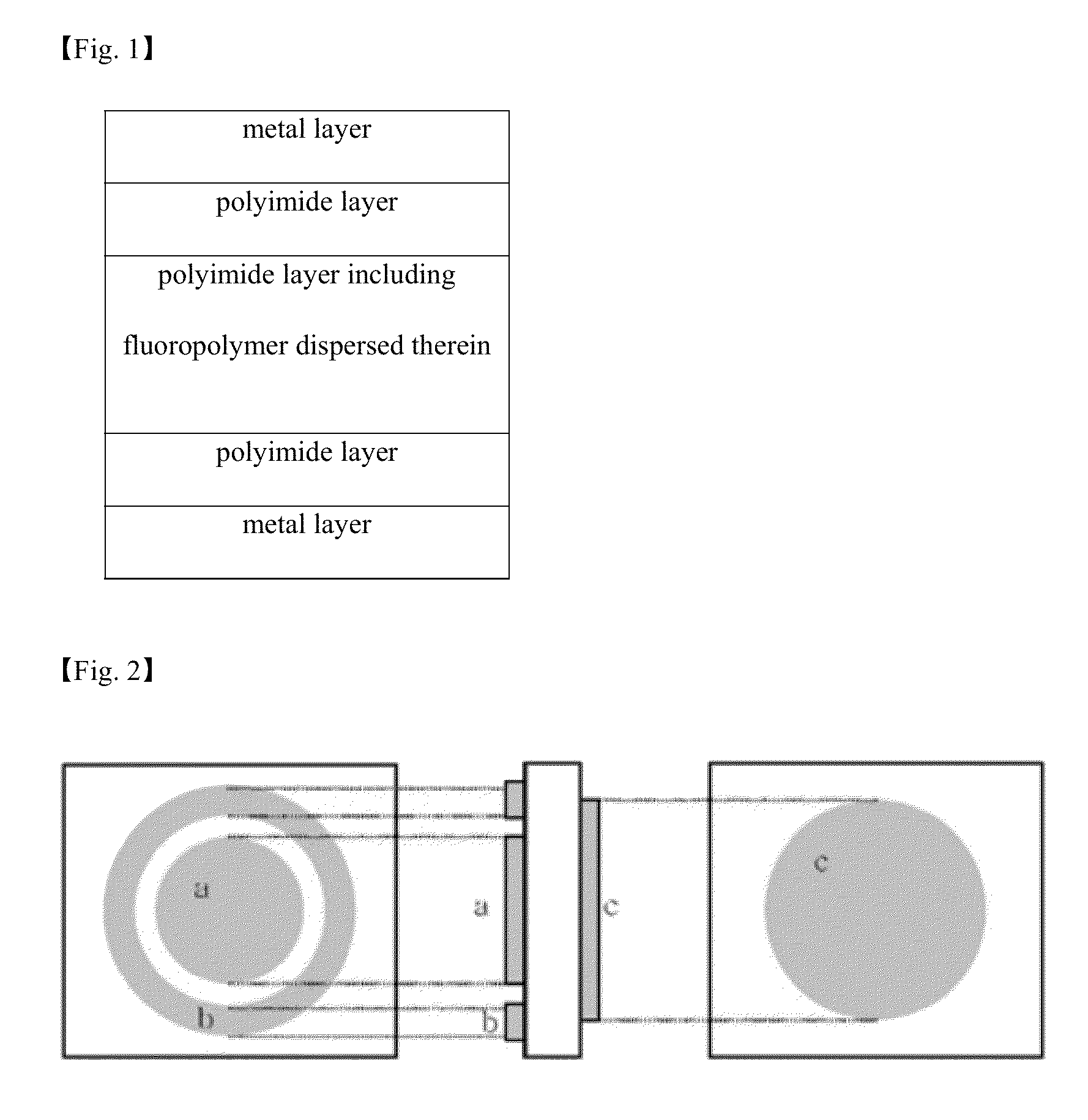
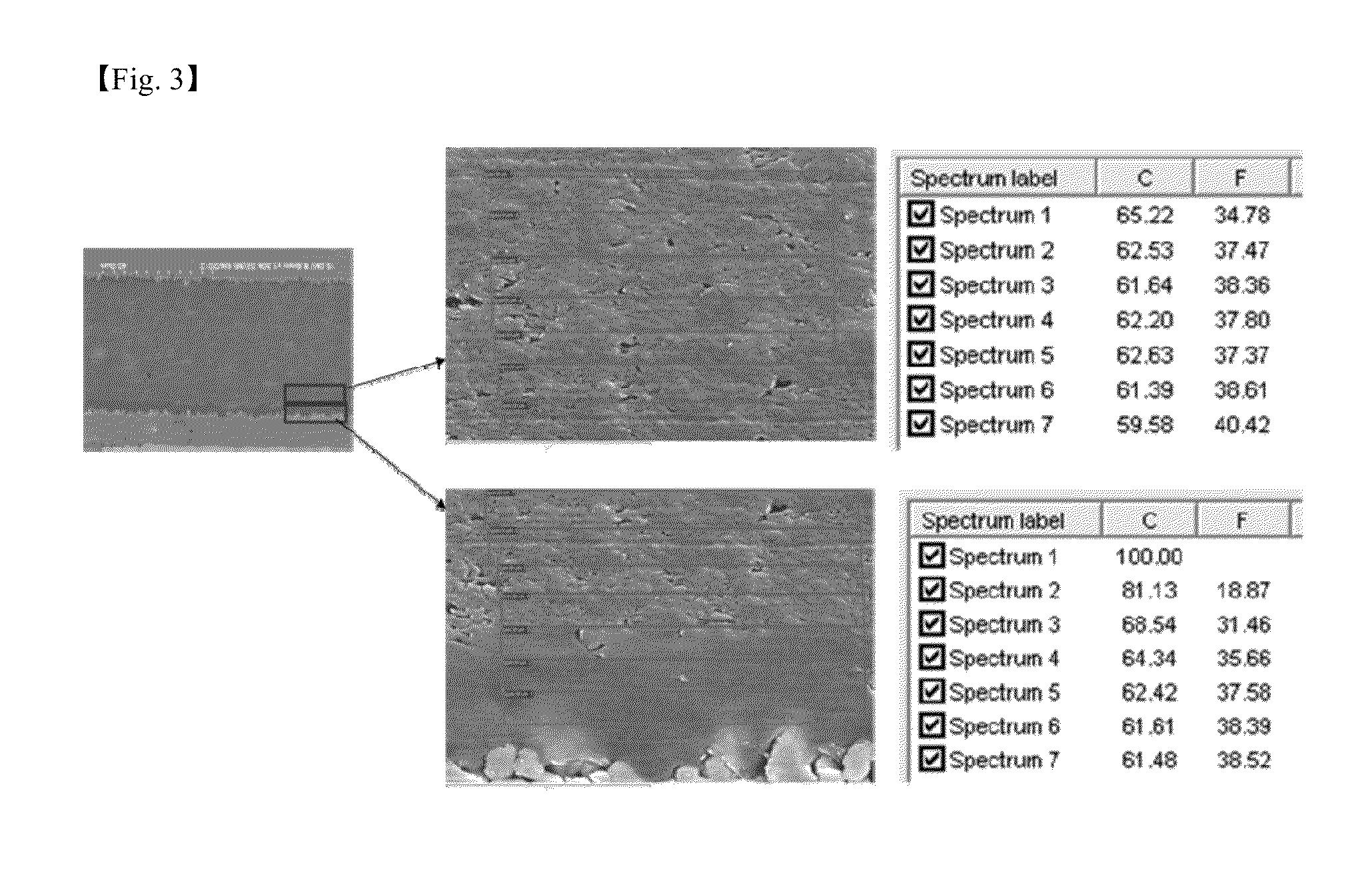
The present invention relates to a flexible metal laminate with low dielectric constant, which may be applied for a substrate for a flexible printed circuit. A flexible metal laminate according to one aspect of the invention includes a first metal layer; a first polyimide layer; a polyimide layer including fluoropolymer dispersed therein, formed on the first polyimide layer; and a second polyimide layer formed on the polyimide layer including fluoropolymer dispersed therein; wherein in the polyimider layer including dispersed fluoropolymer, the content of the fluoropolymer per unit volume is higher at 40 to 60% depth than at 5 to 10% depth of the total thickness from the surface of the polyimide layer.

Description

CROSS REFERENCE TO RELATED APPLICATIONS[0001]This application claims priority from Korean Patent Application No. 10-2012-0098872 filed on Sep. 6, 2012, and claims priority from Korean Patent Application No. 10-2011-0090825 filed on Sep. 7, 2011, all of which are incorporated herein by reference in their entireties for all purposes.FIELD OF THE INVENTION[0002]The present invention relates to a flexible metal laminate containing fluoropolymer. More specifically, the present invention relates to a flexible metal laminate that may be applied for a flexible printed circuit.BACKGROUND OF THE INVENTION[0003]A flexible metal laminate is mainly used as a substrate of a flexible printed circuit board, and it is also used as flat heating element electromagnetic shield material, flat cable, package material, and the like. Among the flexible metal laminates, a flexible copper clad laminate consists of a polyimide layer and a copper foil layer, and it is divided into an adhesive type and a non-ad...

Claims


Application Information

Patent Timeline
IPC IPC(8): B32B15/08B32B37/06B05D3/02B32B3/00B32B7/02
CPCB32B2255/06B32B2255/26B32B2255/28H05K1/024H05K1/036H05K1/0393Y10T428/24355B32B2037/243B32B2311/00B32B2327/12B32B2379/08Y10T428/264Y10T428/24975H05K3/022Y10T428/3154Y10T428/31544Y10T428/31681Y10T428/31721
Inventor PARK, YOUNG-SEOKPARK, SOON-YONGJANG, SE-MYUNG
Owner GUANGDONG SHENGYI SCI TECH
Learn More