
Welded steel pipe for linepipe with high compressive strength and manufacturing method thereof

a technology of compressive strength and welded steel pipe, which is applied in the field of linepipes, can solve problems such as complete suppression, and achieve the effects of high compressive strength, excellent fracture toughness and high strength

Active Publication Date: 2012-11-15
JFE STEEL CORP
View PDF1 Cites 12 Cited by
  • Summary
  • Abstract
  • Description
  • Claims
  • Application Information

AI Technical Summary

Benefits of technology

[0022]Embodiments of the present invention have been made under the above-mentioned circumstances, and it is an object of the present invention to provide a welded steel pipe for a linepipe having high strength and excellent fracture toughness necessary for the application of the steel pipe to an offshore pipeline having a heavy wall thickness, that is, a welded steel pipe for a linepipe with high compressive strength and a heavy wall thickness which can suppress lowering of compressive strength caused by a Bauschinger effect and can exhibit excellent sour resistance performance by optimizing the metal microstructure of a steel plate without requiring particular forming conditions in forming the steel pipe and without requiring heat treatment after pipe making.

Problems solved by technology

(2) High-strength steel manufactured by accelerated cooling, particularly a steel plate having a heavy wall thickness used for an offshore pipeline contains a large amount of alloy elements for acquiring required strength so that the steel plate has high hardenability whereby it is difficult to completely suppress the formation of MA.

Method used


Image

  • Welded steel pipe for linepipe with high compressive strength and manufacturing method thereof

Examples


embodiment

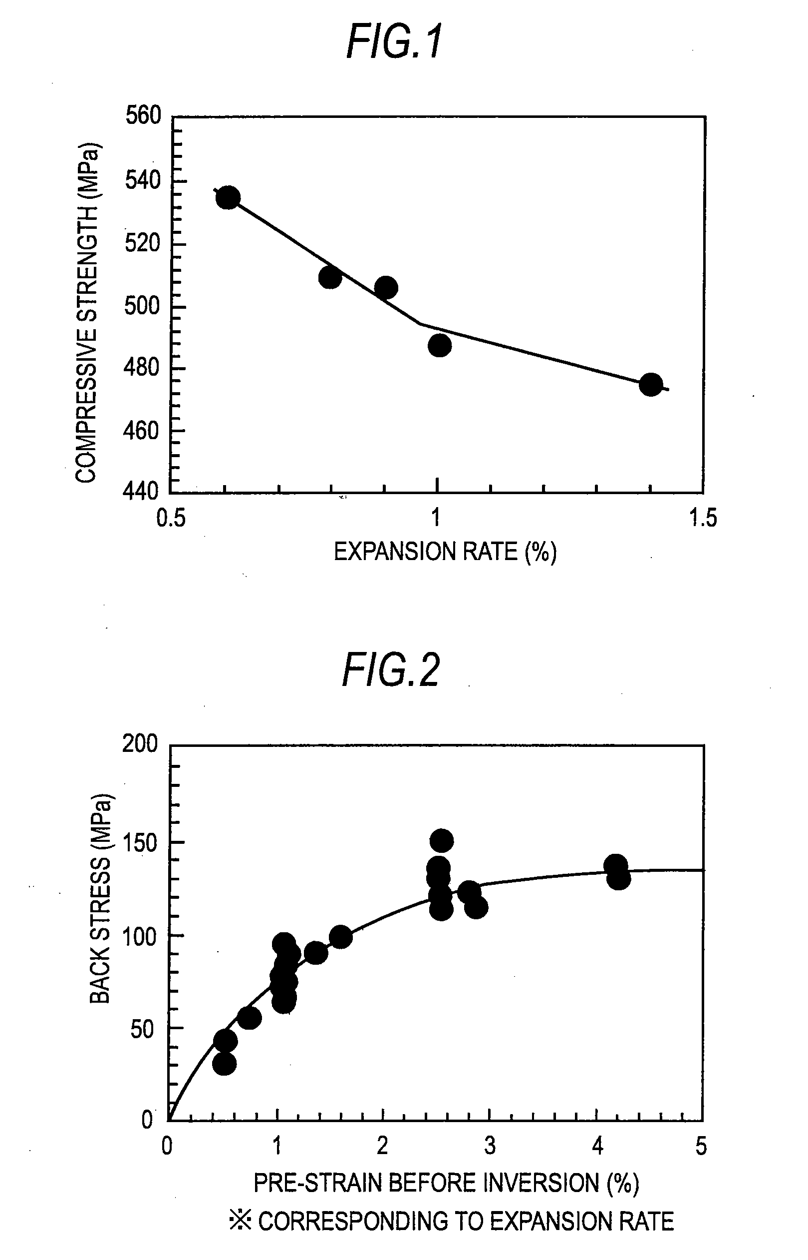
[0096]Slabs are manufactured from steels (kinds of steels A to N) having chemical compositions shown in Table 1 by a continuous casting process, and heavy-wall-thickness steel plates (No. 1 to 24) having plate thicknesses of 22 mm to 34 mm were manufactured using the slabs. Manufacturing conditions of the steel plates are shown in Table 2. In reheating treatment at the time of manufacturing the steel plate, reheating was performed using an induction heating furnace which is mounted on the same line as an accelerated cooling facility. A surface layer temperature at the time of reheating is a surface temperature of the steel plate at an exit of the induction heating furnace, and a steel plate temperature at a point of time that a surface layer temperature and a center temperature become substantially equal to each other after heating is set as the center temperature. Using these steel plates, steel pipes having various diameters were manufactured by a UOE process. An expansion rate at...


PUM

PropertyMeasurementUnit
grain sizeaaaaaaaaaa
temperatureaaaaaaaaaa
surface temperatureaaaaaaaaaa

Abstract

Provided are a steel pipe for a linepipe with high compressive strength and a heavy wall thickness, and a method of manufacturing the same. Lowering of yield stress caused by a Bauschinger effect can be suppressed by optimizing the metal microstructure of a steel plate without requiring particular forming conditions in forming the steel pipe, and without requiring heat treatment after pipe making. A steel pipe has the composition which contains by mass % 0.03 to 0.10% C, 0.30% or less Si, 1.00 to 2.00% Mn, 0.015% or less P, 0.003% or less S, 0.080% or less Al, 0.005 to 0.035% Nb, 0.005 to 0.020% Ti, and Fe and unavoidable impurities as a balance. The steel pipe has metal microstructure where a fraction of bainite is 60% or more, a fraction of rolled ferrite is 5% or less, and a fraction of M-A constituent (MA) is 3% or less.

Description

CROSS-REFERENCE TO RELATED APPLICATIONS[0001]This application is the U.S. National Phase application of PCT / JP2010 / 071528, filed Nov. 25, 2010, and claims priority to Japanese Patent Application No. 2009-267257, filed Nov. 25, 2009, the disclosures of which PCT and priority applications are incorporated herein by reference in their entireties for all purposes.FIELD OF THE INVENTION[0002]The present invention relates to a linepipe for transporting crude oil, a natural gas or the like, and more particularly to a welded steel pipe for a pipe with high compressive strength or a welded steel pipe for a pipe having still higher compressive strength and excellent sour gas resistance suitably used as a linepipe for deep-sea having a heavy wall thickness which is required to exhibit high collapse resistant performance, and a manufacturing method thereof. The compressive strength used in the present invention means, unless otherwise specified, compressive yield strength or 0.5% compressive pr...

Claims


Application Information

Patent Timeline
Patent Type & Authority Applications(United States)
IPC IPC(8): F16L9/00B21D37/16
CPCB23K9/0282B23K9/18C21D8/10C22C38/14C21D2211/002C22C38/06C22C38/12C21D8/105C22C38/02C22C38/04
Inventor NISHIMURA, KIMIHIROISHIKAWA, NOBUYUKITANIZAWA, AKIHIKOSUEYOSHI, HITOSHIHORIE, MASAYUKIKIYOTO, YASUMITSU
Owner JFE STEEL CORP
Learn More