Magnetic recording medium
a recording medium and magnetic recording technology, applied in the field of magnetic recording and assisted magnetic recording, can solve the problems of inability to bring the magnetic head into close proximity to the magnetic recording medium, the inability to perform recording and reproducing operations at a resolution suitable for high density recording
- Summary
- Abstract
- Description
- Claims
- Application Information
AI Technical Summary
Benefits of technology
Problems solved by technology
Method used
Image
Examples
embodiment 1
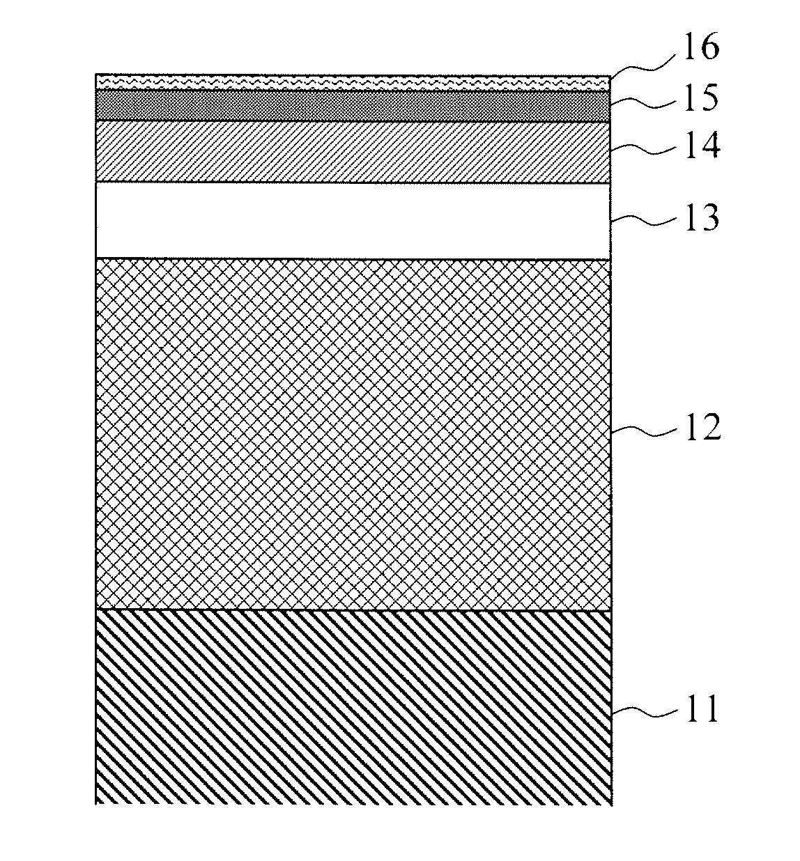
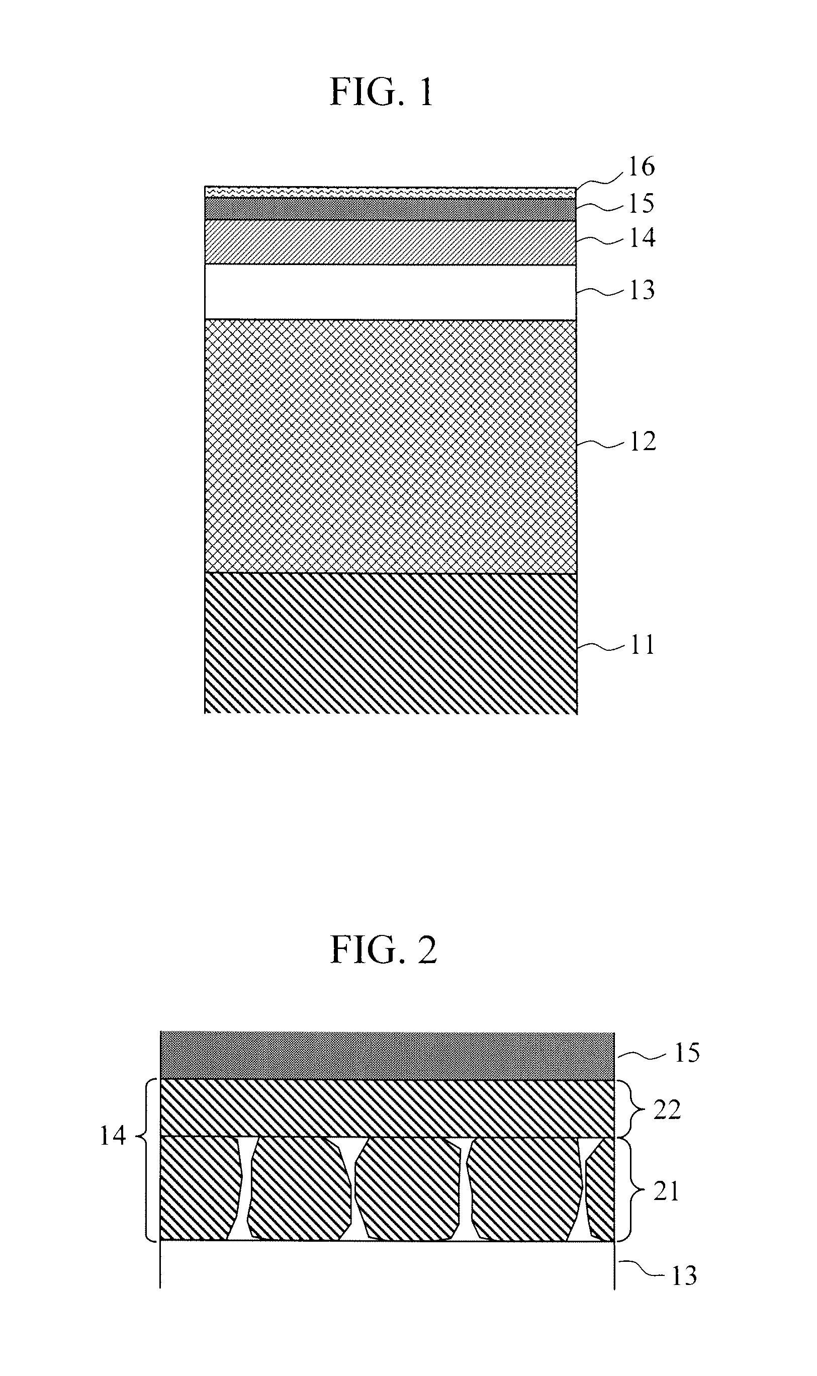
[0036]FIG. 1 shows a schematic drawing of cross section of a magnetic recording medium of this embodiment. The magnetic recording medium of this embodiment has a structure in which, a NiTa alloy layer 12, a MgO oxide layer 13, a magnetic recording layer 14, and a carbon overcoat layer 15 are sequentially formed on a heat resistant glass substrate 11. The heat resistant glass substrate 11 is formed into a toroidal shape to fit for a 2.5-inch-type HDD, and washed before film-forming. A substrate 11 is introduced into an in-line vacuum sputtering apparatus, and each layer is formed using DC and RF sputtering.
[0037]The NiTa alloy layer 12 is formed to have a thickness of 100 nm using a NiTa38 target (the numerical subscript denotes an atomic percent of a ratio of element dosage into the alloy; likewise thereafter). The NiTa alloy layer 12 has an amorphous structure. According to an electron diffraction analysis, a hollow diffraction ring can be observed. The NiTa alloy layer 12 is resis...
embodiment 2
[0057]The magnetic recording medium of this embodiment is fabricated in the material configuration and the film forming condition identical to those of Embodiment 1 except for the FePt capping layer 22. The difference between this embodiment and Embodiment 1 is in that oxides are used, instead of C, as the non-magnetic grain boundary material added to the FePt capping layer 22.
[0058]Two sputtering targets, or a target made only of an Fe45Pt45Ag10 alloy and a target formed by sintering this alloy and the oxides are used for forming the FePt capping layer 22. Three types, or Fe45Pt45Ag10—SiO2, Fe45Pt45Ag10—Ta2 and Fe45Pt45Ag10—Ta2O5 are used as targets including oxides. Here, the oxide dosage into each target is 50 vol. %.
[0059]In a case of representing the dosage of SiO2 in molecular ratio×(mol. %) and volumetric ratio y (vol. %), it is provided that both notations are converted into each other according to a following equation.
y=−0.0348x2+2.98x
[0060]Likewise, in a case of TiO2, it ...
embodiment 3
[0067]The magnetic recording medium of this embodiment is fabricated in conditions substantially equivalent to the laminated structure and the film-forming condition of Embodiment 1. However, an Ag element is not added to the magnetic recording layer 14 (the FePt granular magnetic layer21 and the FePt capping layer 22); an Fe50Pt50−35 vol. % C target and an Fe50Pt50 target are used for forming magnetic recording layer 14. In a case without adding the Ag element, the temperature necessary to order the FePt alloy tends to become high. In this embodiment, the substrate temperature of the FePt granular magnetic layer 21 during film deposition is 500° C. and the post annealing process temperature after depositing the FePt capping layer 22 is 550° C., the temperatures being respectively 50° C. higher.
[0068]A medium in Embodiment 3-1 is fabricated by adding approximately 35 vol. % C to the FePt granular magnetic layer 21 and adding approximately 10 vol. % C to the FePt capping layer 22. A ...
PUM
| Property | Measurement | Unit |
|---|---|---|
| saturated magnetic flux density | aaaaa | aaaaa |
| diameters | aaaaa | aaaaa |
| roughness | aaaaa | aaaaa |
Abstract
Description
Claims
Application Information
 - R&D Engineer
- R&D Manager
- IP Professional
- Industry Leading Data Capabilities
- Powerful AI technology
- Patent DNA Extraction
Browse by: Latest US Patents, China's latest patents, Technical Efficacy Thesaurus, Application Domain, Technology Topic, Popular Technical Reports.
© 2024 PatSnap. All rights reserved.Legal|Privacy policy|Modern Slavery Act Transparency Statement|Sitemap|About US| Contact US: help@patsnap.com


