
Composition and energy storage device

Active Publication Date: 2012-07-19
GENERAL ELECTRIC CO
View PDF1 Cites 6 Cited by
  • Summary
  • Abstract
  • Description
  • Claims
  • Application Information

AI Technical Summary

Problems solved by technology

However, the practical energy density after the first full battery charge is much lower than theoretical value and cycle life of such battery is very short.
However, the above approaches had disadvantages of low working capacity or, in the case of sulfur, non-uniform distribution causing high variability in the battery performance and fast degradation.
However, the above electrodes containing FeS and S in combination with NaX (X=F, Br, I), were not suitable for high current applications because of low working capacity and fast degradation of cells.

Method used


Image

  • Composition and energy storage device
  • Composition and energy storage device
  • Composition and energy storage device

Examples


example 1

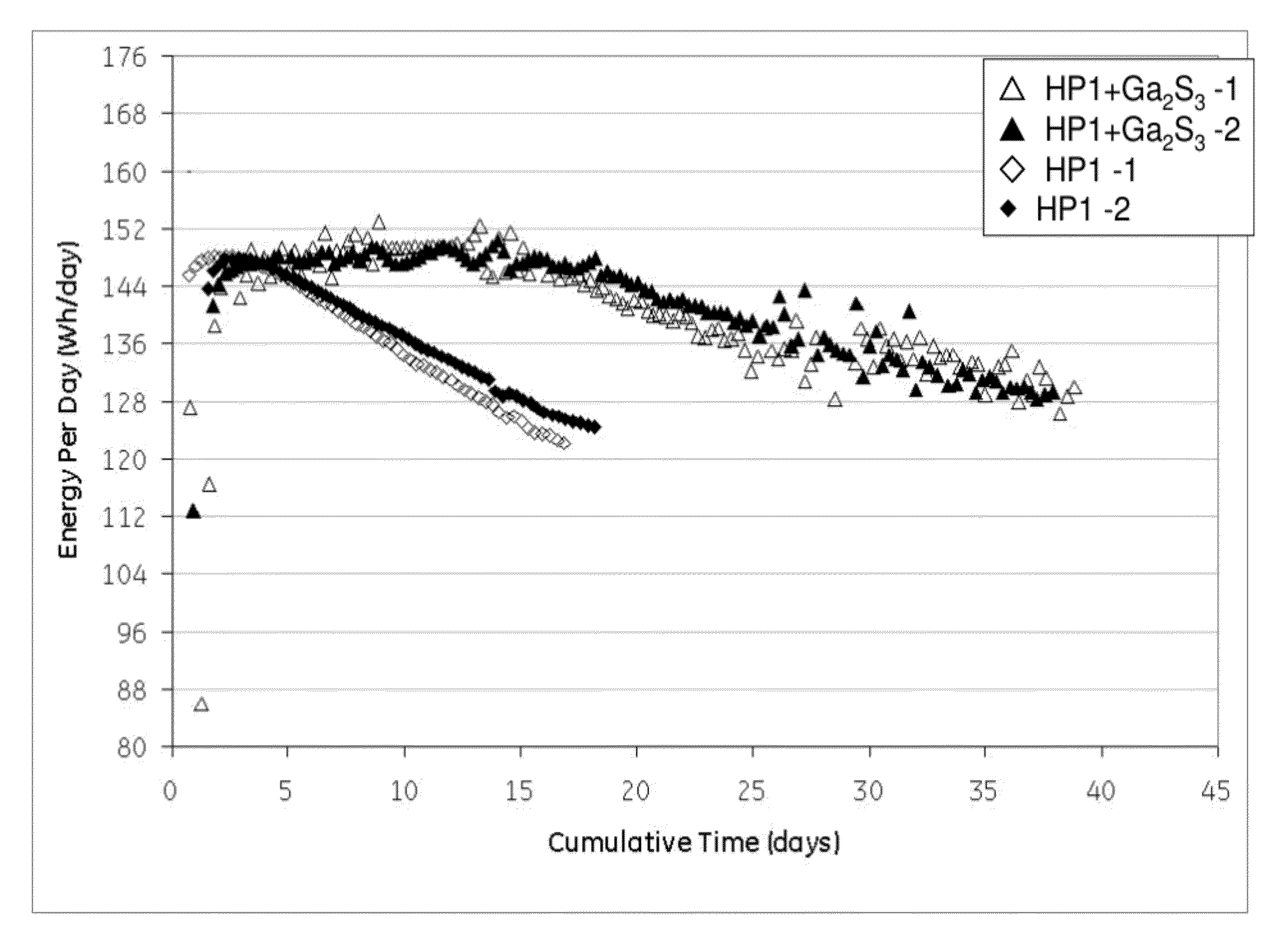
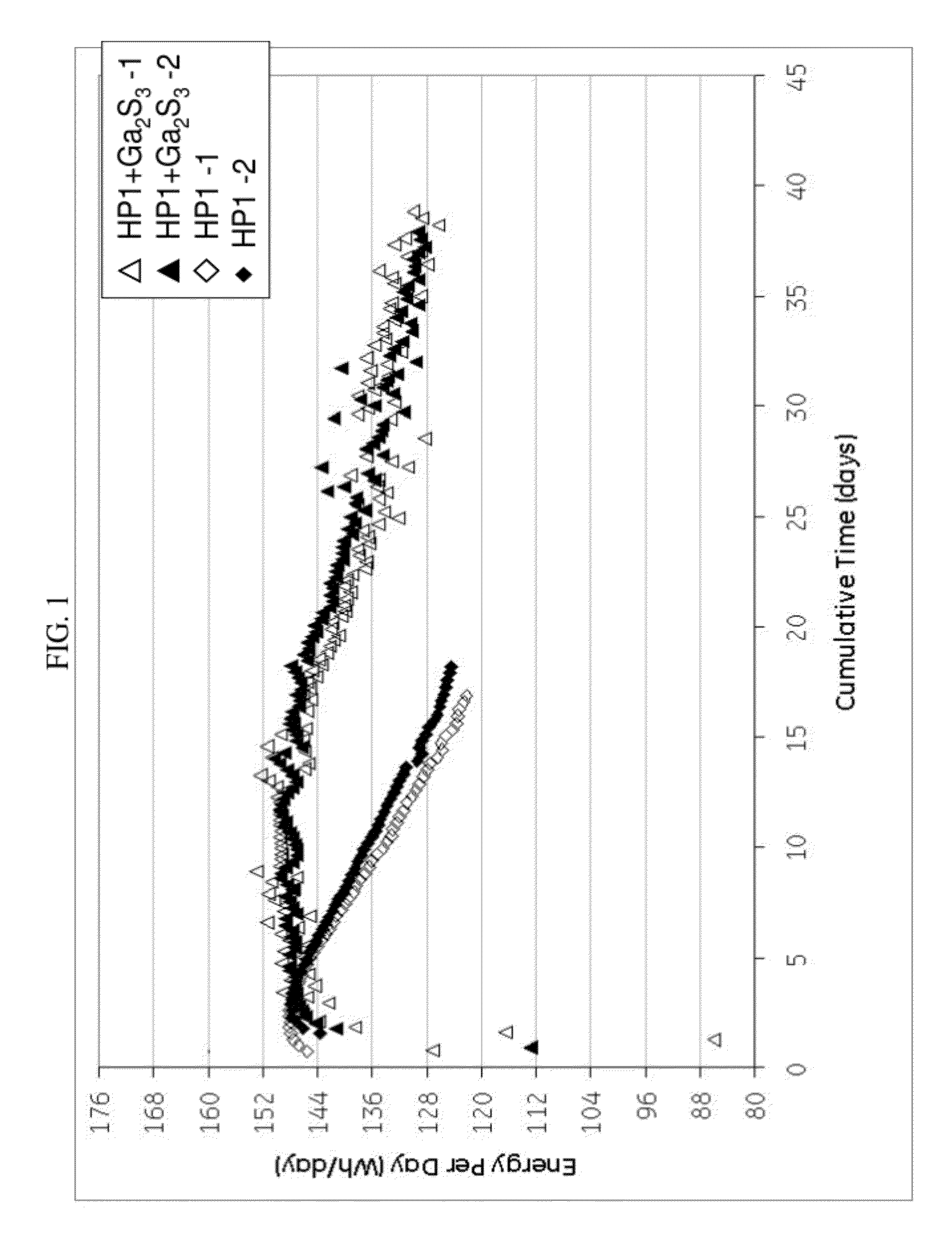
[0065]Cells with similar nickel / iron-sodium chloride cathodes containing no sulfide compound and those containing gallium sulfide were assembled and tested according to the Protocol A. The cathode compositions are shown in Table 1. The single cell test results are illustrated in FIG. 1 showing the energy per day (watt-hours per day (Wh / day)) versus cumulative time in days for a 40% depth of discharge (DoD) at 300° C. As can be seen, the samples with the gallium sulfide, after a period of 10 days, consistently showed a higher energy per day. By day 18 the cells with no gallium sulfide had decreased to less than 125 Wh / day, while the cells with gallium sulfide had an energy of greater than 144 Wh / day. Actually, even at 35 days, the cells with the gallium sulfide had an energy of greater than 128 Wh / day. In other words, the life of the cell was unexpectedly nearly doubled.

example 2

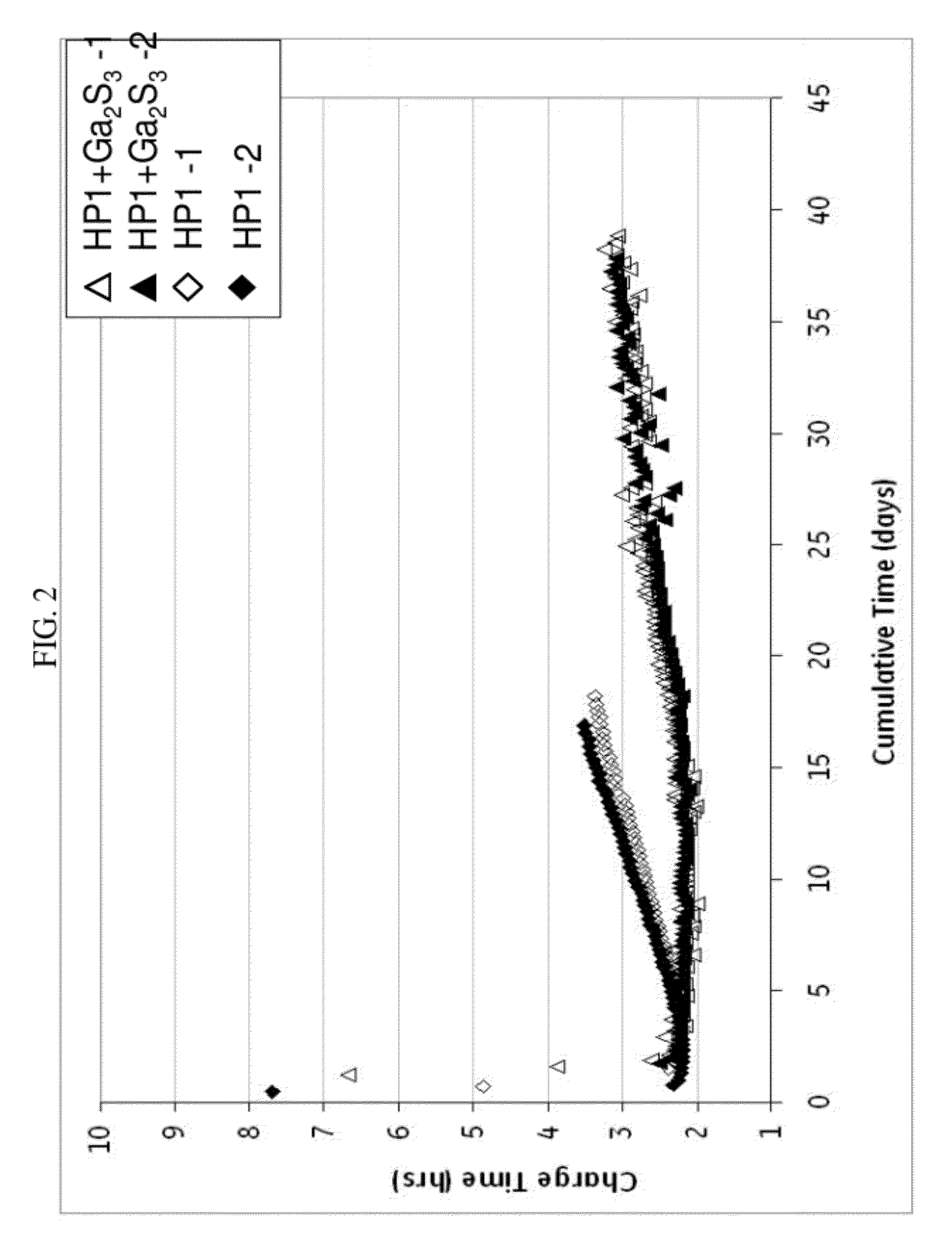
[0066]In FIG. 2, the charge time in hours for the same cells as in FIG. 1 was determined. Similar to FIG. 1, the cells comprising a cathode composition with gallium sulfide significantly outperformed the cells with a cathode composition without gallium sulfide. Here, the charge time reached over 3 hours for HP1 by day 14, but Ga2S3 did not reach a charge time of 3 hours until day 27, and not consistently until day 33. Furthermore, by day 18, HP1 had exceeded a charge time of 3.5 in one case and 3.3 in the other. Unexpectedly, Ga2S3, in more than 36 days, did not exceed 3.3 hours charge time. With the gallium sulfide in the cathode composition, a charge time of less than 3 hours can be maintained for greater than or equal to 20 days, and even greater than or equal to 25 days, and a charge time of less than 3.4 can be maintained for greater than or equal to 20 days, greater than or equal to 30 days, and even greater than or equal to 35 days.

example 3

[0067]Cells with similar nickel / iron-sodium chloride cathodes containing no sulfide compound and those containing antimony sulfide were assembled and tested according the Protocol A. The cathode compositions are shown in Table 1. The single cell test results are illustrated in FIG. 3 showing the energy per day (Wh / day) versus cumulative charge and discharge times in days for an 80% DoD at 300° C. As can be seen, the samples with the antimony sulfide, after a period of 10 days, consistently showed a higher energy per day under both 80% DoD. By day 25 the cells with no antimony sulfide had about 10 Wh / day lower energy than the cells with the antimony sulfide. In other words, the life of the cell was unexpectedly nearly doubled.


PUM


Abstract

In one embodiment, a cathode composition comprises a transition metal and / or a transition metal salt, wherein the transition metal is selected from the group consisting of nickel, iron, cobalt, chromium, manganese, molybdenum, zinc, and antimony, and a combination comprising at least one of the foregoing; an alkali metal halide; an electrolyte salt comprising an alkali metal halide and a metal halide; and a sulfide compound selected from the group consisting of gallium sulfide, antimony sulfide, and a combination comprising at least one of the foregoing. An energy storage device comprising the electrode composition is also provided.

Description

BACKGROUND OF THE INVENTION[0001]The invention includes embodiments that relate to an electrode composition. The invention includes embodiments that relate to an electrode for an energy storage device.[0002]Metal chloride batteries with molten sodium anode and beta-alumina solid electrolyte are widely employed for energy storage applications. The energy storage application can include mobile applications due to their high energy density and long cycle life. To be applicable for mobile applications like hybrid locomotives or plug-in electric vehicles (PHEV), the sodium nickel chloride battery should tolerate power surges (high currents) at both battery charging and discharging without loss in the working capacity and the cycle life. The sodium nickel chloride batteries are used because of the high theoretical energy density (790 Wh / kg) in addition to their ability to operate over a wide temperature range. The cathode of such battery is built from nickel metal, sodium chloride NaCl an...

Claims


Application Information

Patent Timeline
IPC IPC(8): H01M10/0563H01M4/58H01M10/36H01M50/434H01M50/463
CPCH01M2/1646H01M2/18H01M4/136Y02E60/122H01M4/5815H01M4/582H01M10/052H01M4/364Y02E60/10H01M50/463H01M50/434
Inventor KNIAJANSKI, SERGEIMESHKOV, ANDREY IVANOVICHSOLOVEICHIK, GRIGORII LEVVALLANCE, MICHAEL ALAN
Owner GENERAL ELECTRIC CO
Learn More