
Process

a technology of ferroelectric materials and process, which is applied in the field of new, can solve the problems of difficult piezoelectric pbnbsub>2, cracking of ceramics, poor piezoelectric properties, etc., and achieve the effects of improving product properties, high density, and controlling microstructur

Active Publication Date: 2012-04-19
CERPOTECH
View PDF3 Cites 7 Cited by
  • Summary
  • Abstract
  • Description
  • Claims
  • Application Information

AI Technical Summary

Benefits of technology

[0073]It is a preferred feature of this invention that the primary particles or crystallites formed by the spray pyrolysis process are already of a size which can be used without any milling procedure. It may however by necessary to break up agglomerates of particles which can form during spray pyrolysis. This breaking up process is a low energy process and can be considered different to conventional higher energy milling. Whilst break up of the particles is typically achieved using a milling machine, the energy required to break up an agglomerate of primary particles is very much lower than the energy required to mill a large particle.
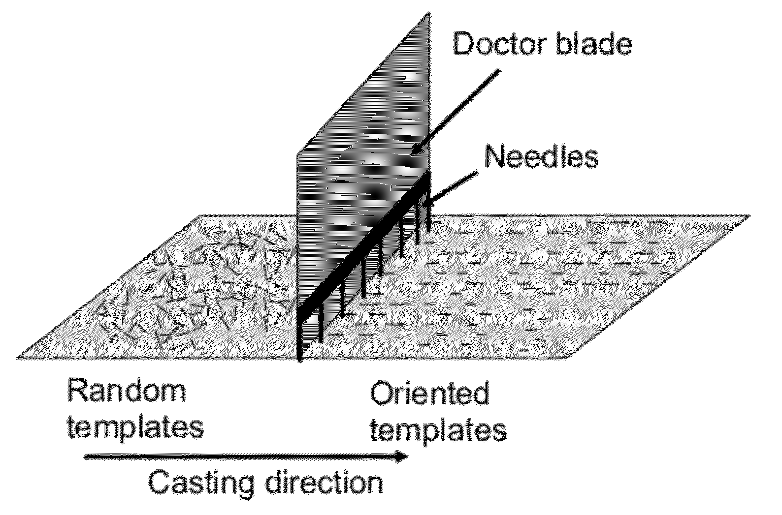
[0147]The alignment of the needle-like templates is crucial both for a strong crystal orientation and for the final density of the ceramic. This is due to the higher green-density achieved by ordering the templates by the modified tape casting process.

Problems solved by technology

However, it is difficult to fabricate piezoelectric PbNb2O6-type ceramics because of the formation of a stable non-ferroelectric rhombohedral phase on cooling to room temperature.
This problem has been addressed by rapid cooling from the sintering temperature, however, there is a further problem associated with this type of material, the large volume change due to phase transformation on cooling below the Curie point, leading to cracking of the ceramic.
However, the piezoelectric properties are not good because of a very low poling efficiency.
On application of the external field the spontaneous polarisation within each domain of the ceramic is orientated in the direction of the applied field, leading to a net polarisation in the poling direction, but the domains in a ceramic cannot fully align along the poling axis because the orientation of the polarisation is restricted by the symmetry of the crystal structure.
However, the traditional synthesis route for ceramic powders by firing oxides of the different cations gives a coarse powder which needs a very high sintering temperature.
This is a particular problem here due to the volatilization of the alkali metals above about 1000° C., and poor sinterability has been the main obstacle for the development of these materials.
The main challenge is the provision of single phase, fine-grained and dense ceramics, preferably with a high degree of preferential orientation in order to obtain improved ferroelectric properties.
At this high temperature, coarsening of the particles occurs and they become large.
To break down these primary particles requires a lot of energy and breaking them down to sub micron level, for example less than 500 nm, is problematic.

Method used


Image

  • Process
  • Process
  • Process

Examples


example 2

KNbO3 Nanopowders Prepared by Spray Pyrolysis

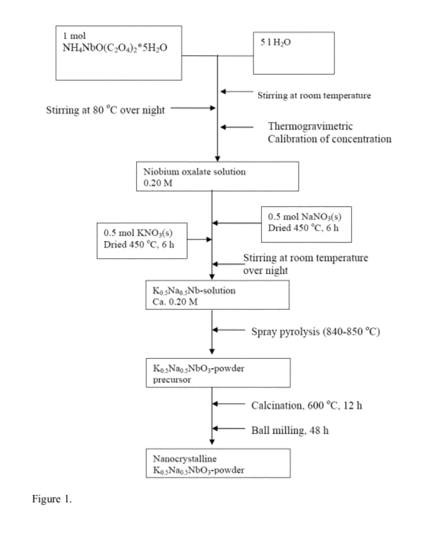
[0170]The aqueous precursor solution was prepared in a similar manner as for Example 1, except that 1 mol of potassium nitrate was added instead of half a mole of sodium and potassium nitrate. The precursor solution was spray pyrolyzed as described under Example 1 and the resulting powder precursor was treated in a similar manner. The morphology of the KNbO3 precursor powder and powder calcined at 800° C. followed by ball milling for 48 hours is shown in FIG. 8. The powder after calcination and milling consists of submicron particles. The x-ray diffractogram in FIG. 9 shows that the powder is single phase. Onset of densification is recorded to be at 1000° C.

example 3

NaNbO3Nanopowders Prepared by Spray Pyrolysis

[0171]The aqueous precursor solution was prepared in a similar manner as for Example 2, except that 1 mole of sodium nitrate was added instead of one mole of potassium nitrate. The precursor solution was spray pyrolyzed as described under Example 1 and the resulting powder precursor was treated in a similar manner. The morphology of the NaNbO3 precursor powder and powder calcined at 800° C. followed by ball milling for 48 hours is shown in FIG. 10. The powder after calcination and milling consists of submicron particles. The x-ray diffractogram in FIG. 11 shows that the powder is single phase. Onset of densification is recorded to be at 1200° C.

example 4

The Fabrication of the Anisometric KNN (K0.5Na0.5NbO3)

[0172]The fabrication of the anisometric KNN templates was performed using two separate steps. The non-perovskite K2Nb4O11 compound with high aspect ratio was first prepared by molten salt synthesis at 1000° C. for 6 h in air. The needle-like particles were converted to KNN by chemical conversion in molten KCl at 800° C. for 30min. A SEM image of the KNN templates prepared by chemical conversion is shown in FIG. 15a. The templates had a needle-like shape with dimensions 0.5-1 μm in thickness and 15-20 μm in length. The templates had an orthorhombic crystal structure with lattice parameters a=3,961 Å, b=5,670 Å, c=5,698 Å and the high aspect ratio along the [001] direction.


PUM

PropertyMeasurementUnit
Temperatureaaaaaaaaaa

Abstract

A process for the preparation of a niobium compound of formula (I):DαNbβEγO3-δ  (I)whereinD is an alkali metal (e.g. Li, Na, K, Rb, Cs and / or Fr), alkaline earth metal (such as Ba, Ca, Mg and / or Sr), La and / or Bi and may be present as a mixture of two or more metals;E is Ta, Sb and / or Fe and may be present as a mixture of two or more metals;α is a positive numberβ is a positive numberγ is zero or a positive numberδ is a number 0≦δ≦0.5;and wherein the formula (I) has the perovskite or tungsten bronze structure;comprising spray pyrolising a solution, for example an aqueous solution, comprising metal (D) ions, Nb ions and if present, metal (E) ions.

Description

FIELD[0001]The present invention relates to a new process for the manufacture of ferroelectric materials in the form of alkali metal niobates or mixed niobium-tantalum oxide solid solutions. The nanoscale niobates and mixed niobium-tantalum oxide products of the process are also encompassed by the invention, as is their use in the manufacture of electronic devices, in particular transducers, ultrasound diagnostic equipment, gas ignitors, accelerometers, displacement transducers and piezoelectric transformers, actuators, sensors and the devices thus obtained.BACKGROUND[0002]Ferroelectric materials have many important applications as functional materials in electronics and optics. A large number of ferroelectric ceramics exploit properties that are an indirect consequence of ferroelectricity, such as dielectric, piezoelectric, pyroelectric and electro-optic properties. With the development of ceramic processing and thin film technology, many new applications have emerged. The biggest ...

Claims


Application Information

Patent Timeline
IPC IPC(8): H01L41/187B29C35/02C01D1/02B29C39/02C01D17/00C01D15/02
CPCC01G33/00H01L41/1873C01G35/00C01P2002/30C01P2002/34C01P2002/72C01P2002/88C01P2004/03C01P2004/10C01P2004/54C01P2004/62C04B35/495C04B35/62645C04B35/6267C04B2235/3201C04B2235/3205C04B2235/3227C04B2235/3251C04B2235/3272C04B2235/3298C04B2235/81C01G33/006H10N30/8542H10N30/853
Inventor MADARO, FRANCESCOGRANDE, TOREINARSRUD, MARIANNWIIK, KJELL
Owner CERPOTECH
Learn More