Process for using catalyst with rapid formation of iron sulfide in slurry hydrocracking
a technology of iron sulfide and hydrocracking, which is applied in the direction of physical/chemical process catalysts, metal/metal-oxide/metal-hydroxide catalysts, other chemical processes, etc. it can solve the problem of limiting the rate at which iron sulfide can form, and achieve less hydrogen sulfide, less hydrogen sulfide, and efficient reaction
- Summary
- Abstract
- Description
- Claims
- Application Information
AI Technical Summary
Benefits of technology
Problems solved by technology
Method used
Image
Examples
example 1
[0047]A feed suitable for SHC is characterized in Table I. Unless otherwise indicated, this feed was used in all the Examples.
TABLE IVacuum BottomsTest(975° F.+)Specific Gravity, g / cc1.03750API gravity−0.7ICP MetalsNi, wt. ppm143V, wt. ppm383Fe, wt. ppm68.8Microcarbon residue, wt-%25.5C, wt-%80.3H, wt-%9.0N, wt-%0.4Total N, wt. ppm5744Oxygen, wt-% in organics0.78Sulfur, wt-%7Ash, wt-%0.105Heptane insolubles, wt-%16.1Pentane insolubles, wt-%24.9Total chloride, mass ppm124Saybolt viscosity, Cst 150° C.1400Saybolt viscosity, Cst 177° C.410
[0048]“ICP” stands for Inductively Coupled Plasma Atomic Emissions Spectroscopy, which is a method for determining metals content.
example 2
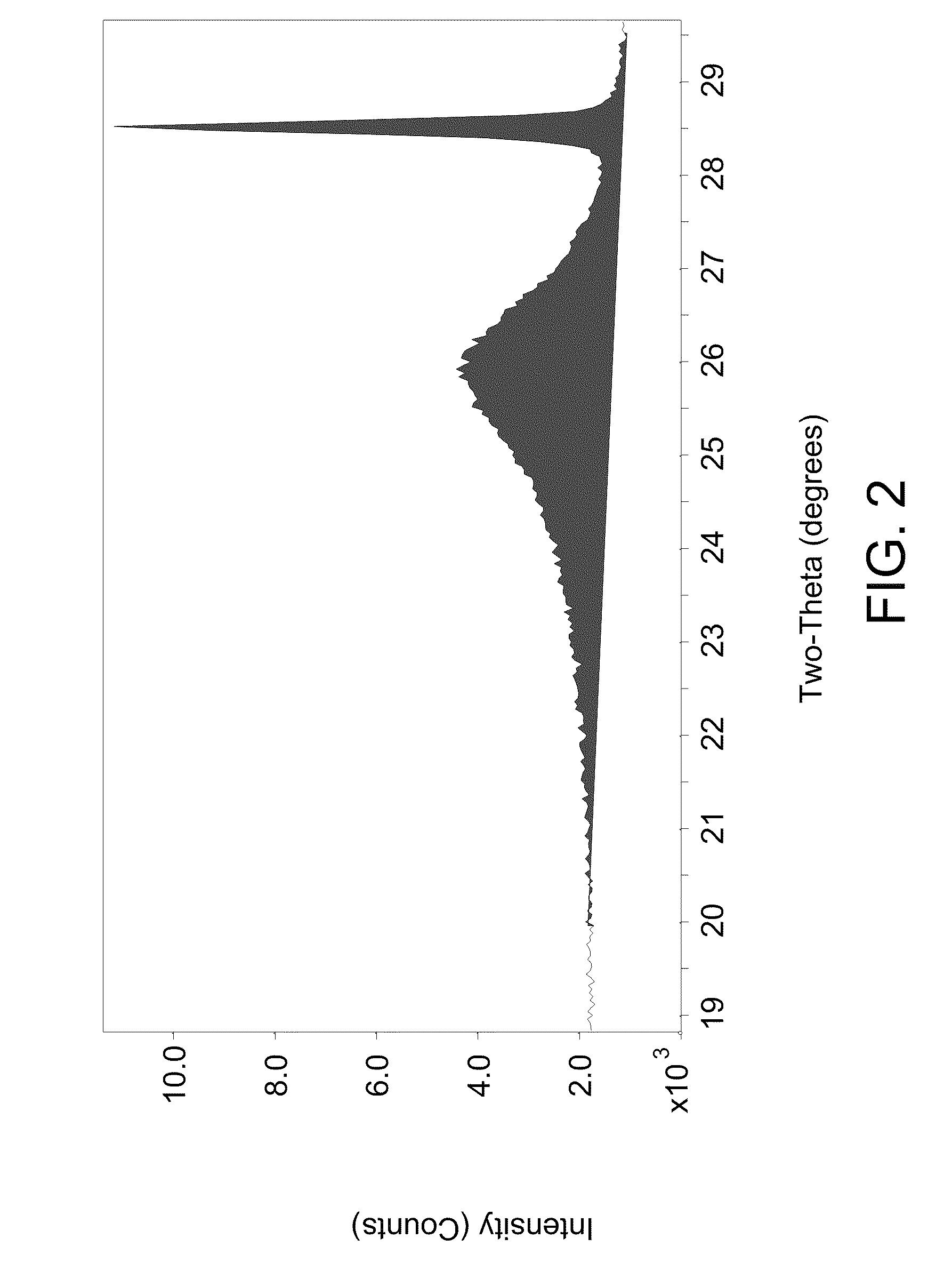
[0049]A TIOR sample from an SHC reaction using heavy oil feed from Example 1 and 0.7 wt-% iron content on iron sulfate monohydrate catalyst as a percentage of non-gaseous materials in the SHC reactor was analyzed for mesophase using an XRD method. A sample of SHC product material was blended with toluene, centrifuged and the liquid phase decanted. These steps were repeated on the remaining solids. The solids remaining were then dried in a vacuum oven at 90° C. for 2 hours. Silicon standard was added to the sample to give a concentration of 5.3 wt-% by adding silicon solid and acetone solvent to a sample of TIOR and slurried together with a mortar and pestle. The acetone evaporated out of the slurry to leave a solid comprising TIOR blended with silicon standard. An approximately 1 gram sample of the solid sample with blended standard was spread onto a XRD sample holder and placed into the XRD instrument and scanned using parameters of 2.0 / 70.0 / 0.04 / 10 (sec). The XRD instrument was a ...
example 3
[0051]In this example, we examined the ability of iron in iron sulfate monohydrate to convert to the active iron sulfide. Iron sulfate monohydrate was mixed with vacuum resid of Example 1 at 450° C. and 2000 psi (137.9 bar) in an amount such that 2 wt-% iron was present relative to the non-gaseous materials in the reactor. The temperature was chosen because it is the optimal temperature for pitch conversion for sulfur monohydrate catalyst. The semi-continuous reaction was set up so that hydrocarbon liquid and catalyst remained in the reactor; whereas, 6.5 standard liters / minute (sl / m) of hydrogen were fed through the reaction slurry and vented from the reactor. X-ray diffraction (XRD) characterization of solid material separated from vacuum resid feed during different stages of the reaction shows that the transformation of Fe(SO4).H2O to FeS is comparatively slow. FIG. 4 shows XRD patterns from samples taken from the semi-continuous reaction at various time intervals. FIG. 4 shows i...
PUM
| Property | Measurement | Unit |
|---|---|---|
| temperature | aaaaa | aaaaa |
| temperature | aaaaa | aaaaa |
| temperature | aaaaa | aaaaa |
Abstract
Description
Claims
Application Information
 - R&D
- Intellectual Property
- Life Sciences
- Materials
- Tech Scout
- Unparalleled Data Quality
- Higher Quality Content
- 60% Fewer Hallucinations
Browse by: Latest US Patents, China's latest patents, Technical Efficacy Thesaurus, Application Domain, Technology Topic, Popular Technical Reports.
© 2025 PatSnap. All rights reserved.Legal|Privacy policy|Modern Slavery Act Transparency Statement|Sitemap|About US| Contact US: help@patsnap.com


