
Energy conversion materials fabricated with boron nitride nanotubes (BNNTs) and BNNT polymer composites

a technology of boron nitride nanotubes and composite materials, which is applied in the direction of piezoelectric/electrostrictive device material selection, device material selection, material nanotechnology, etc., can solve the problems of poor mechanical properties, low electroactive coefficient, and high toxicity

Active Publication Date: 2011-08-11
NASA +1
View PDF10 Cites 26 Cited by
  • Summary
  • Abstract
  • Description
  • Claims
  • Application Information

AI Technical Summary

Benefits of technology

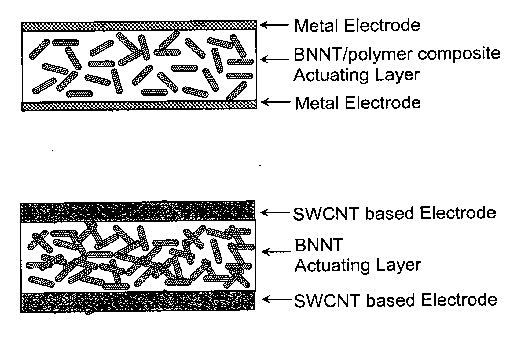
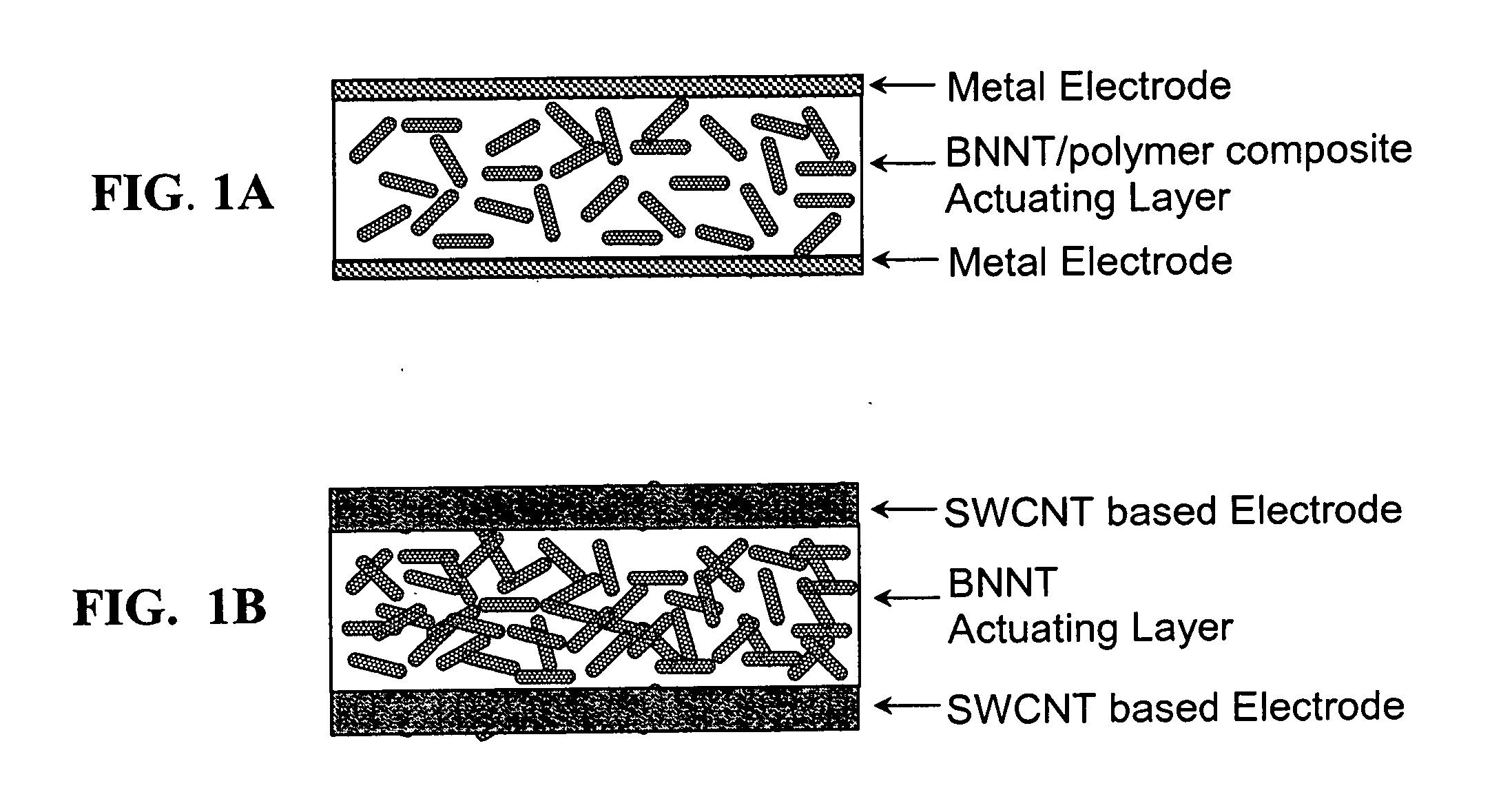
[0016]In one embodiment, a method for forming a boron nitride nanotube/polymer nanocomposite film, includes synthesizing a high temperature piezoelectric polyimide, combining a boron nitride nanotubes solution with the high temperature piezoelectric polyimide, using a polymer as a matrix and synthesizing a boron nitride nanotube/polyimide nanocomposite film as an electroactive layer. The polymer is dianhydride, pyromellitic dianhydride and the high temperature piezoelectric polyimide is synthesized from a diamine, 2,6-bis(3-aminophenoxy)benzonitrile ((β-CN)APB) and a dia

Problems solved by technology

Electroactive ceramics such as lead zirconate titanates (PZT), lead-lanthanum zirconate titanate (PLZT), and niobium-lead zirconate titanate (PNZT) have very high piezoelectric coefficients, but have poor mechanical properties (i.e., are brittle) and high toxicity.
However, they have relatively low electroactive coefficients and poor thermal properties.
This is due to the fact that the dipoles in the polymer do not align along the applied electric field efficiently because of limited chain mobility within the imidized closed ring structure.
However, there are still limitations to the use of electroactive polyimide composites in many applications.
This limits the use of the composites for high voltage devices.
Many electroactive materials have been proposed, but they still have problems of poor mechanical / thermal properties or unsatisfactory electroactive performance.
However, no experimental result of the piezoelectric properties of BNNTs or BNNT composites has been reported as yet.

Method used


Image

  • Energy conversion materials fabricated with boron nitride nanotubes (BNNTs) and BNNT polymer composites
  • Energy conversion materials fabricated with boron nitride nanotubes (BNNTs) and BNNT polymer composites
  • Energy conversion materials fabricated with boron nitride nanotubes (BNNTs) and BNNT polymer composites

Examples


Embodiment Construction

[0027]The following detailed description is of the best presently contemplated mode of carrying out the invention. This description is not to be taken in a limiting sense, but is made merely for the purpose of illustrating general principles of embodiments of the invention.

[0028]Since the first theoretical prediction of the existence of boron nitride nanotubes (BNNTs) in 1994 and the first experimentally synthesized BNNT report by Zettl's group in 1995, several types of BNNT synthesis methods have been reported. Recently, a new and conceptually simple method of producing extraordinarily long, highly crystalline BNNTs was demonstrated. BNNTs are thought to possess high strength-to-weight ratio, high thermal stability (up to about 800° C. in air), piezoelectricity, and radiation shielding capabilities. Nakhmanson's theoretical analysis predicted that the piezoelectric coefficient of BNNTs can be higher than that of poly(vinylidene fluoride) (PVDF) or poly(vinylidene fluoride-trifluoro...


PUM

PropertyMeasurementUnit
Percent by massaaaaaaaaaa
Temperatureaaaaaaaaaa

Abstract

Electroactive actuation characteristics of novel BNNT based materials are described. Several series of BNNT based electroactive materials including BNNT / polyimide composites and BNNT films are prepared. The BNNT based electroactive materials show high piezoelectric coefficients, d13, about 14.80 pm / V as well as high electrostrictive coefficients, M13, 3.21×10⁻¹⁶ pm2N2. The BNNT based electroactive materials will be used for novel electromechanical energy conversion devices.

Description

CROSS REFERENCE TO RELATED APPLICATION[0001]The present application claims priority from U.S. Provisional Application Ser. No. 61 / 278,866, filed Oct. 13, 2009.STATEMENT REGARDING FEDERALLY SPONSORED RESEARCH OR DEVELOPMENT[0002]The U.S. Government has a paid-up license in this invention and the right in limited circumstances to require the patent owner to license others on reasonable terms as provided for by the terms of Cooperative Agreement No. NCC-1-02043 awarded by the National Aeronautics and Space Administration.BACKGROUND OF THE INVENTION[0003]1. Field of the Invention[0004]The present invention relates to high performance energy conversion devices such as sensors and electromechanical actuators, and, more particularly to energy conversion devices manufactured from boron nitride nanotubes and BNNT / polyimide composite materials.[0005]2. Description of Related Art[0006]Electroactive materials have been studied extensively in the last few decades for use in a variety of applicat...

Claims


Application Information

Patent Timeline
IPC IPC(8): H05K13/00H01L41/26H01L41/24B82Y30/00B82Y99/00H01L41/45
CPCB82Y30/00H01L41/37Y10T29/49002B82Y40/00G01R29/14H01L41/293Y10T29/42Y10T29/49005Y10T29/49155H10N30/092C08J5/18C08K3/38Y10S977/778C08K2003/382H10N30/063H10N30/00H10N30/702H10N30/704
Inventor KANG, JIN HOPARK, CHEOLHARRISON, JOYCELYN S.SMITH, MICHAEL W.LOWTHER, SHARON E.KIM, JAE-WOOSAUTI, GODFREY
Owner NASA
Learn More