
Method for Producing a Component

a manufacturing method and technology for components, applied in the direction of railway components, nuclear engineering, plasma technology, etc., can solve the problems of high cost, time-consuming and expensive, and the difficulty of mechanical processing or machining of such a composite material

Active Publication Date: 2013-10-24
EADS DEUT GMBH
View PDF15 Cites 87 Cited by
  • Summary
  • Abstract
  • Description
  • Claims
  • Application Information

AI Technical Summary

Benefits of technology

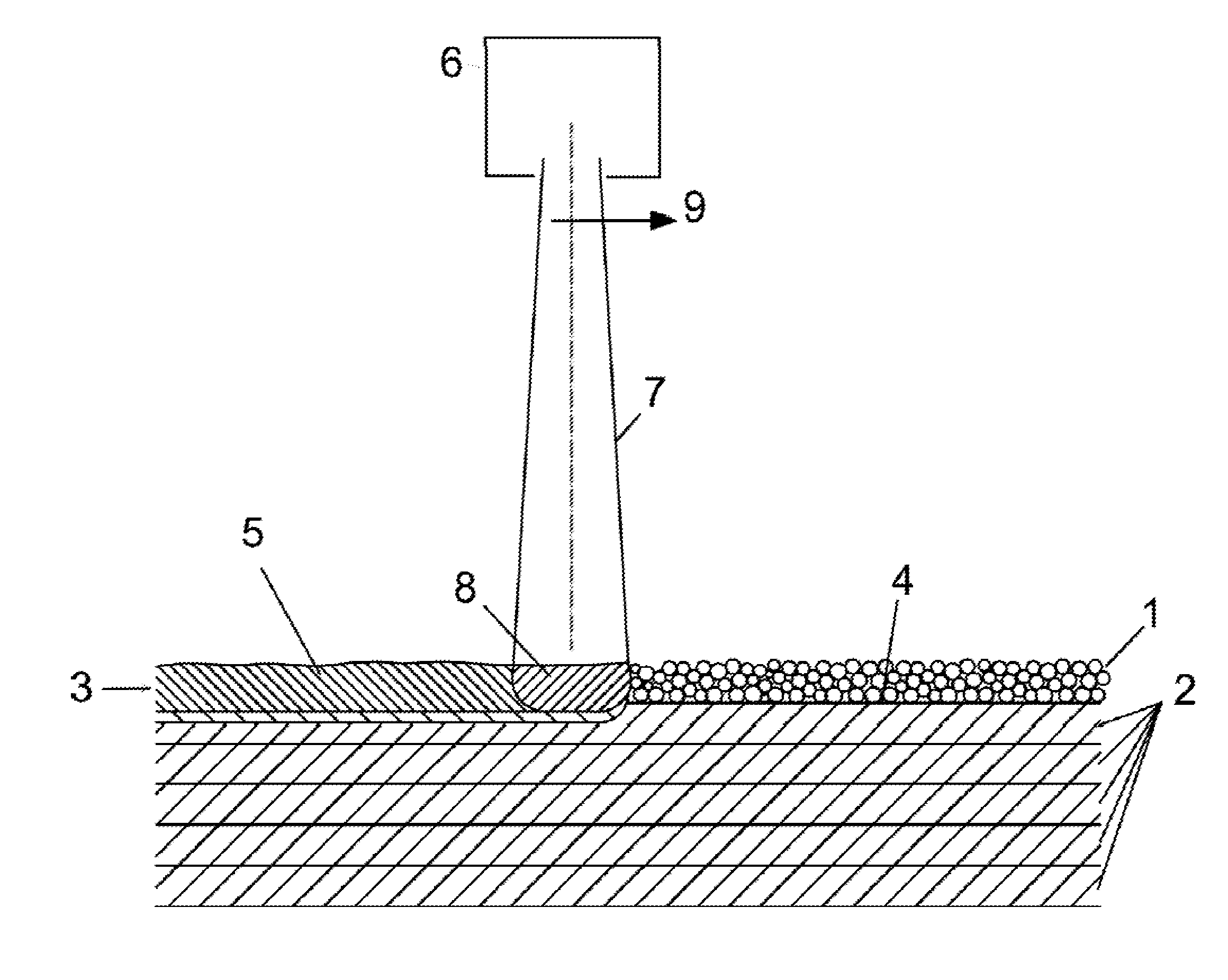
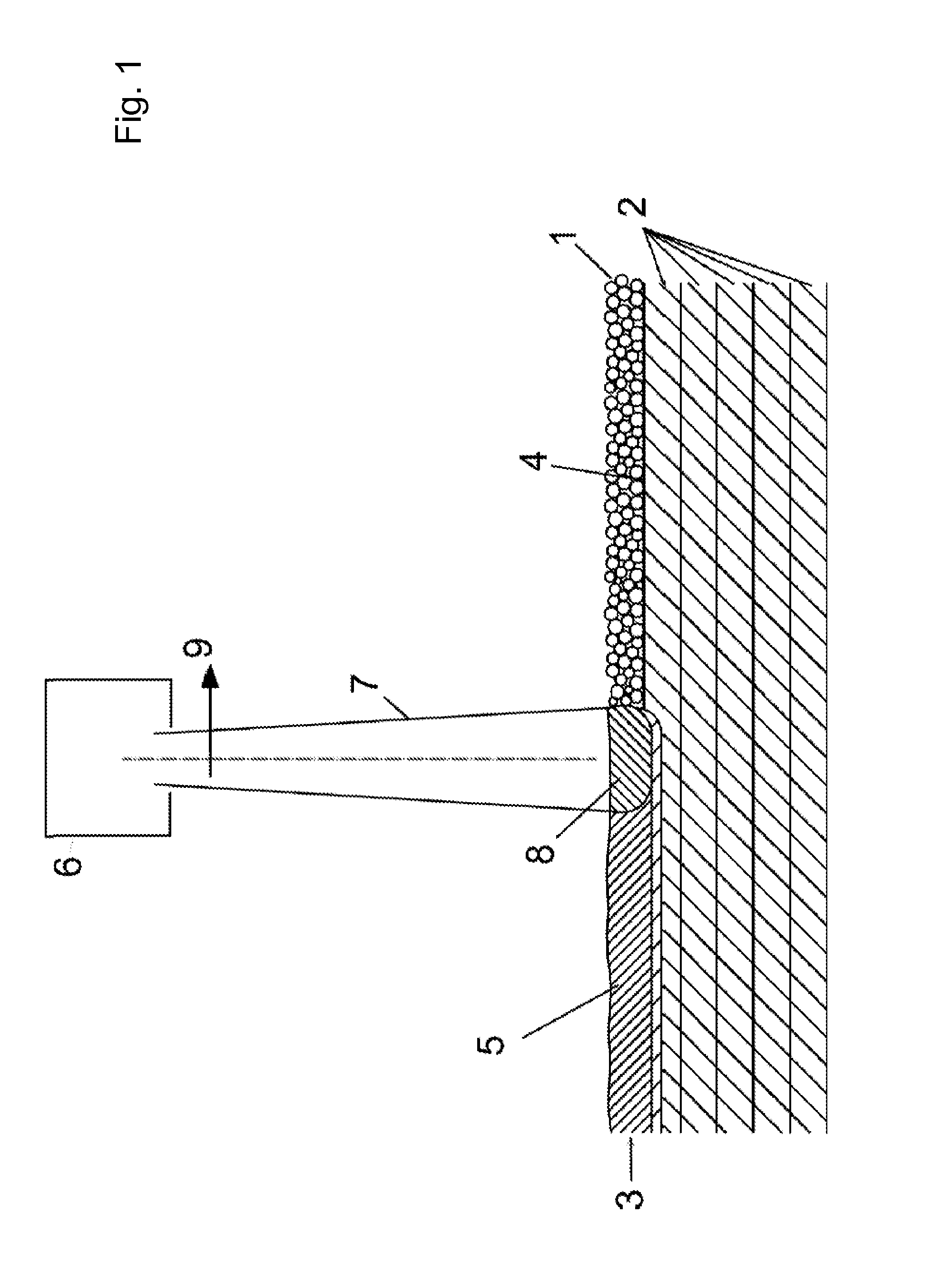
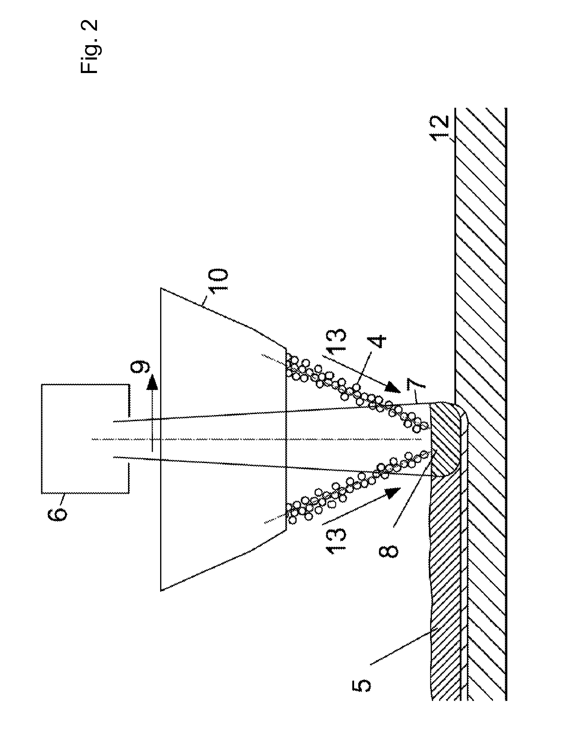
The present invention provides a method for creating a highly heat-conducting structure in a near net shape by layer-by-layer construction. The method involves applying a layer section of a composite material of a metal and / or a metal alloy and particles of a highly heat-conducting material, such as diamond or cubic boron nitride, in a predetermined area on a base layer by melting the metal or metal alloy and cooling it. The highly heat-conducting material can be embedded in the metal or metal alloy matrix. The method can be used to manufacture a heat-conducting, near-net shape component by applying additional layers of composite material to a base layer. The resulting composite material has improved thermal conductivity and can be used in various applications requiring heat conduction.

Problems solved by technology

If convection cooling is impossible and radiant cooling is inadequate, the heat must be dissipated by thermal conduction of suitable heat-conducting materials.
However, the density of Ag, Cu and Au is comparatively high, namely greater than 9 g / cm3, so that heat sinks made of these metals definitely increase the total weight of a device containing them, which is often undesirable.
However, only elements having a simple and usually flat geometry can be manufactured economically in this way because the mechanical processing or machining of such a composite material is extremely difficult, time-consuming and expensive.

Method used


Image

  • Method for Producing a Component
  • Method for Producing a Component
  • Method for Producing a Component

Examples


example 1

Milling Aluminum-Diamond Powder

[0114]Diamond powder (size 70-90 μm) and pure aluminum powder (grain size 2 (stabilized with Y2O3). Since aluminum is deposited on the balls and milling cups, the aluminum must be added in amounts greater than the theoretical amount in order to arrive at the desired aluminum-diamond mixture composition. The milled powder may then be used directly for generative manufacturing or preferably may be screened first to remove large particles.

example 2

Production of Aluminum-Diamond Thermal Conductivity Samples in a Powder Bed

[0115]In the following example, thermal conductivity samples of 70 vol % diamond powder (size 70-90 μm) and 30 vol % pure aluminum (grain size <45 μm) were manufactured in a laser-based powder bed process. The laser power was 300 W and the scan rate was 800 mm / s. The samples had a diameter of approximately 14 mm and were approximately 5 mm thick. They were then machined to a diameter 12.3 mm and a thickness of 2.6 mm and their surfaces were polished. As shown in FIG. 6, the thermal conductivity values of the aluminum-diamond samples are significantly higher in comparison with those of pure aluminum.


PUM

PropertyMeasurementUnit
sizeaaaaaaaaaa
sizeaaaaaaaaaa
sizeaaaaaaaaaa

Abstract

A method for manufacturing a component having increased thermal conductivity through layer-by-layer construction. At least one section of the component is constructed by applying a layer section having predetermined dimensions of a composite material of a metal and / or a metal alloy and particles of a highly heat-conducting material, including diamond and / or cubic boron nitride, in a predetermined area on a base layer by melting the metal or the metal alloy a heat source, in such a way that the metal and / or metal alloy form(s) within the predetermined dimensions a cohesive matrix, in which particles of the highly heat-conducting material are embedded, and then cooling.

Description

CROSS-REFERENCE TO RELATED APPLICATIONS[0001]The present application is a continuation of PCT International Application No. PCT / DE2011 / 002102, filed Dec. 12, 2011, and claims priority under 35 U.S.C. §119 to German Patent Application No. 10 2010 055 201.1, filed Dec. 20, 2010, the entire disclosure of these applications is herein expressly incorporated by reference.FIELD OF THE INVENTION[0002]Exemplary embodiments of the present invention relate to a method for manufacturing a component having an increased thermal conductivity through layer-by-layer construction and a composite material, i.e., a laminated material manufactured layer by layer, a component that can be manufactured by this method and a composite material that can be manufactured by this method.BACKGROUND OF THE INVENTION[0003]Many industrial components and processes, for example, electronic components and processes, require a rapid and reliable removal of heat during operation in order to prevent overheating and theref...

Claims


Application Information

Patent Timeline
Patent Type & Authority Applications(United States)
IPC IPC(8): B05D3/06B32B5/16
CPCB05D3/06B32B5/16B05D3/065C22C26/00B22F2998/10Y10T428/12014Y10T428/12146B33Y10/00Y02P10/25B22F12/43B22F10/25B22F10/22B33Y70/10B22F10/64B22F3/15
Inventor BRANDL, ERHARDSANDER, JOERGSCHOBERTH, ACHIM
Owner EADS DEUT GMBH
Learn More