Process for production and use of carbonitride mixture particles or oxycarbonitride mixture particles
a technology of carbonitride and mixture particles, which is applied in the field of production and use of metal carbonitride mixture particles or metal oxycarbonitride mixture particles, can solve the problems of difficult processing of carbonitrides to different shapes in later steps, large particles obtained, and difficult to obtain carbonitride powder, etc., to achieve uniform particle size distribution, excellent properties, and uniform composition
- Summary
- Abstract
- Description
- Claims
- Application Information
AI Technical Summary
Benefits of technology
Problems solved by technology
Method used
Image
Examples
example 1
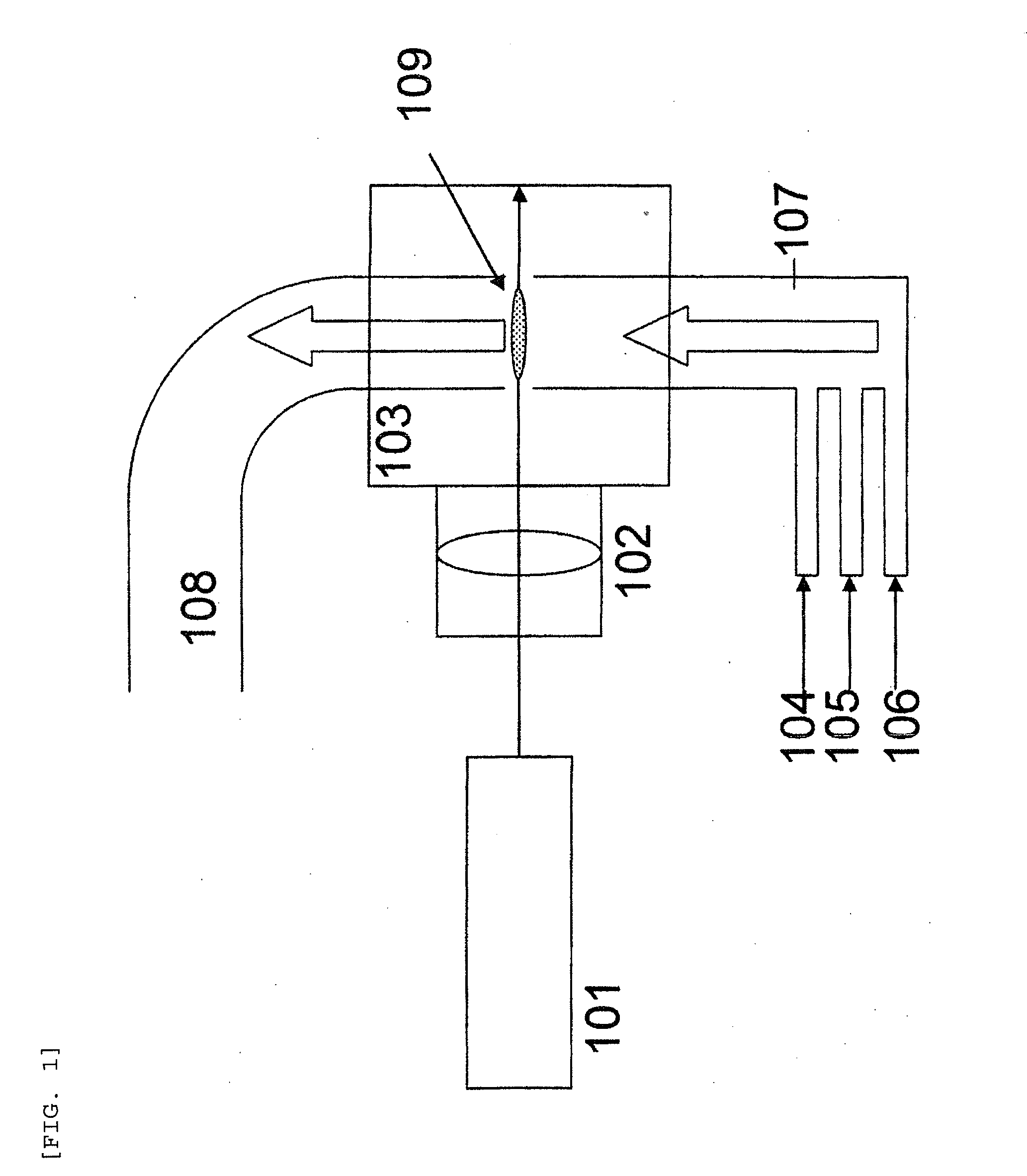
[0093]Carbonitride mixture particles were produced using a laser pyrolysis apparatus as illustrated in FIG. 1 under the following conditions. Into a 0.1 m3 volume chamber, there were fed 20000 sccm (sccm=standard cubic centimeter per minute) of nitrogen as a carrier gas preheated to 200° C., 1000 sccm of methane as a carbon source preheated to 200° C., 5000 sccm of ammonia as a nitrogen source preheated to 200° C., and 2 g (10.5 mmol) per minute of titanium tetrachloride as a metal compound material preheated to 200° C. The chamber pressure was 200 Torr.
[0094]The laser used was a CO2 laser, and the power was 1200 W. The laser light was focused to the reaction zone using a condensing lens. The titanium-containing carbonitride mixture particles generated at the reaction zone were collected through an outlet connected with a dry pump. The carbonitride mixture particles had an average particle diameter of 25 nm. The particle diameter distribution was σ=2 nm.
[0095]The sample obtained had...
example 2
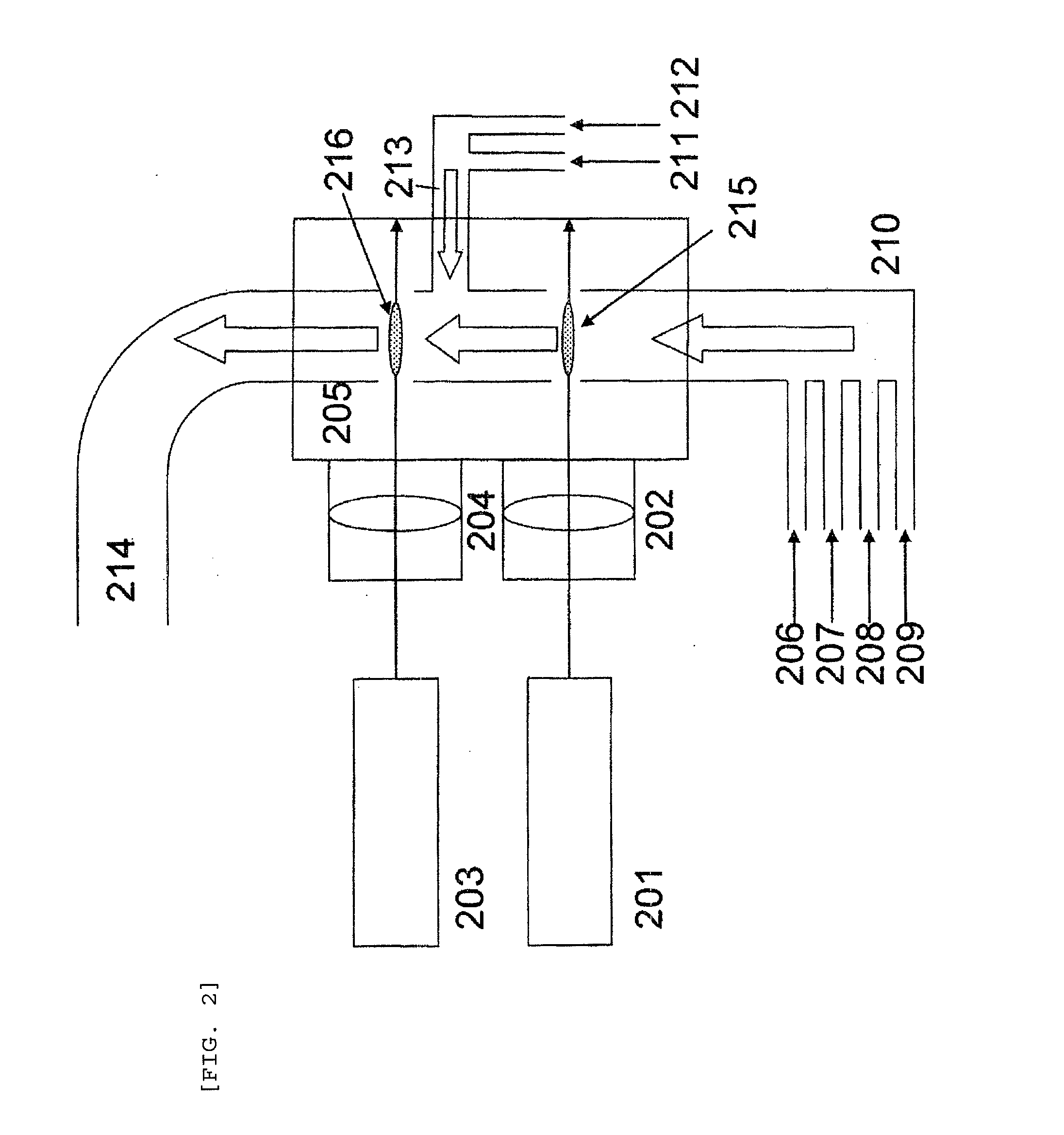
[0096]Oxycarbonitride mixture particles were produced using a laser pyrolysis apparatus as illustrated in FIG. 2 under the following conditions. Into a 0.2 m3 volume chamber having two reaction zones, there were fed 30000 sccm of nitrogen as a carrier gas preheated to 200° C., 7000 sccm of ammonia as a nitrogen source preheated to 200° C., and 4 g (17.5 mmol) per minute of titanium ethoxide as a metal compound material preheated to 200° C.
[0097]Laser light was emitted from a CO2 laser at a power of 1200 W and was focused to the first reaction zone using a condensing lens.
[0098]Further, 10000 sccm of nitrogen as a carrier gas preheated to 200° C. and 1 g per minute of water as an oxygen source were supplied to the second reaction zone. Laser light was emitted from a CO2 laser at a power of 1100 W and was focused to the second reaction zone using a condensing lens.
[0099]The chamber pressure was 200 Torr.
[0100]The titanium-containing oxycarbonitride mixture particles generated at the s...
example 3
[0102]Oxycarbonitride mixture particles were produced using a laser pyrolysis apparatus as illustrated in FIG. 2 under the following conditions. Into a 0.2 m3 volume chamber having two reaction zones, there were fed 30000 sccm of nitrogen as a carrier gas preheated to 200° C., 21000 sccm of ammonia as a nitrogen source preheated to 200° C., and 6 g (18.9 mmol) per minute of niobium ethoxide as a metal compound material preheated to 200° C. Laser light was emitted from a CO2 laser at a power of 1200 W and was focused to the first reaction zone using a condensing lens.
[0103]Further, 10000 sccm of hydrogen as a carrier gas and 1 g per minute of water as an oxygen source were supplied to the second reaction zone. Laser light was emitted from a CO2 laser at a power of 1100 W and was focused to the second reaction zone using a condensing lens.
[0104]The chamber pressure was 200 Torr.
[0105]The niobium-containing oxycarbonitride mixture particles generated at the second reaction zone were co...
PUM
| Property | Measurement | Unit |
|---|---|---|
| Particle diameter | aaaaa | aaaaa |
| Electrical conductor | aaaaa | aaaaa |
Abstract
Description
Claims
Application Information
 - R&D
- Intellectual Property
- Life Sciences
- Materials
- Tech Scout
- Unparalleled Data Quality
- Higher Quality Content
- 60% Fewer Hallucinations
Browse by: Latest US Patents, China's latest patents, Technical Efficacy Thesaurus, Application Domain, Technology Topic, Popular Technical Reports.
© 2025 PatSnap. All rights reserved.Legal|Privacy policy|Modern Slavery Act Transparency Statement|Sitemap|About US| Contact US: help@patsnap.com


