
Vacuum Pyrolytic Gasification And Liquefaction To Produce Liquid And Gaseous Fuels From Biomass

Inactive Publication Date: 2011-01-20
CHAMPAGNE GARY E
View PDF52 Cites 43 Cited by
  • Summary
  • Abstract
  • Description
  • Claims
  • Application Information

AI Technical Summary

Benefits of technology

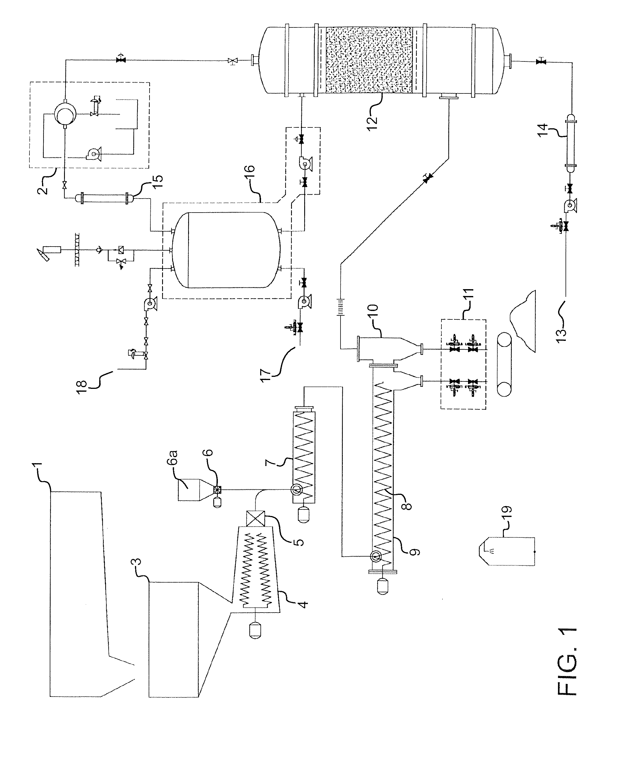
[0007]A biofuel production method, a biofuel production catalyst and a biofuel production system are provided for converting biomass and other carbonaceous feedstock materials to one or more liquid biofuels that may be used to power internal combustion engines and for other energy production purposes. The feedstock is combined with a consumable catalyst and subjected to a vacuum pyrolytic gasification and liquefaction process to produce one or more biofuel end products. The constituents of the biofuel end products may include light liquid fuels having a carbon content of C7-C11 (gasoline range fuels), medium weight liquid fuels having a carbon content of C12-C15 (kerosene range fuels) and heavy liquid fuels having a carbon content of C16-C20 (diesel range fuels). Gaseous biofuels may also be produced and recovered for use.
[0008]According to an example embodiment, the biofuel production method may include combining a feedstock comprising the carbonaceous material with a consumable catalyst to produce a feedstock/catalyst mixture. The feedstock/catalyst mixture may be subjected to a vacuum pyrolytic gasification process wherein the mixture is heated under selected conditions of temperature and vacuum pressure to produce a gaseous effluent comprising one or more hydrocarbon fractions. The gaseous effluent may be subjected to a liquefaction process that includes one or more condensation operations that isolate and remove the desired liquid biofuels and any non-condensable gaseous biofuel products that remain.
[0009]An example biofuel production catalyst may comprise a zeolite material. The zeolite may be combined with a clay material, such as kaolin. Some or all of amorphous silica, alumina and aluminum phosphate may also be present. One or more rare earth elements may likewise be added.

Problems solved by technology

Each the foregoing methods have significant limitations that have prevented mass commercialization, or which have only been commercialized with costly economic subsidies.
Biodiesel production via transesterification is limited for several reasons, including high cost per gallon, the creation of a glycerol waste stream requiring disposal, and reliance on methyl alcohol in a 1:1 ratio with each gallon of biodiesel produced.
Liquid ethanol is limited by high cost per gallon and the use of food feed stocks such as corn in competition with human consumption.
Also, an ethanol fuel content above 15% by volume has been shown to damage present internal combustion engines which further decreases economic viability.
The Fischer Tropsch process is limited by high cost per gallon and high capital cost per gallon.
This method is only used in very large scale immobile plant operations.
The fixed catalyst bed is also easily poisoned and polluted, and is very expensive.

Method used


Image

  • Vacuum Pyrolytic Gasification And Liquefaction To Produce Liquid And Gaseous Fuels From Biomass
  • Vacuum Pyrolytic Gasification And Liquefaction To Produce Liquid And Gaseous Fuels From Biomass
  • Vacuum Pyrolytic Gasification And Liquefaction To Produce Liquid And Gaseous Fuels From Biomass

Examples


working examples

Example 1

[0045]For this example, the feedstock was comprised of a 50 / 50 mix (by weight) of dried salt water algae and flocked wood comprising pine saw dust (⅜ in. particle size or less) and FOG (fats, oils, greases) in the form of yellow grease. The algae had a 40% lipid content largely comprising C16 and C18 fatty acid groups. The wood-FOG mixture contained (by weight) 60% wood and 40% FOG, with the latter containing heavy chains up to C46. This mixture was prepared by combining the saw dust with heated yellow grease in the feedstock preparation subsystem 1. Following dewatering, the excess grease was removed, leaving the flocked feedstock component with a 60% wood / 40% FOG weight ratio. Forty-five (45) pounds of the dried algae was combined with forty-five (45) pounds of the flocked wood-FOG mixture to produce 90 pounds of feedstock. The feedstock mixture had a water content of less than 5% water content and an energy content of 11,500-13,000 BTU per pound.

[0046]The consumable cat...

example 2

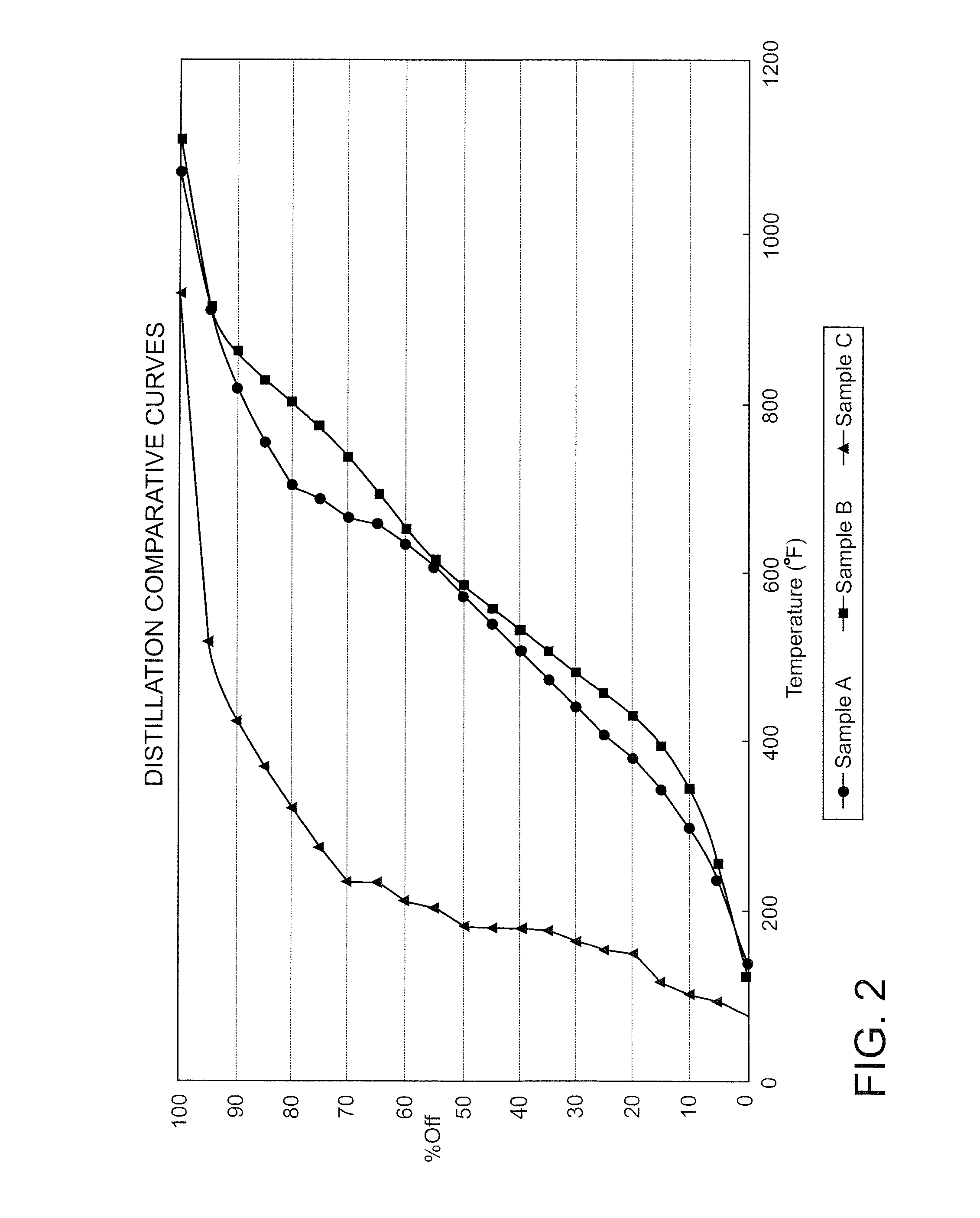
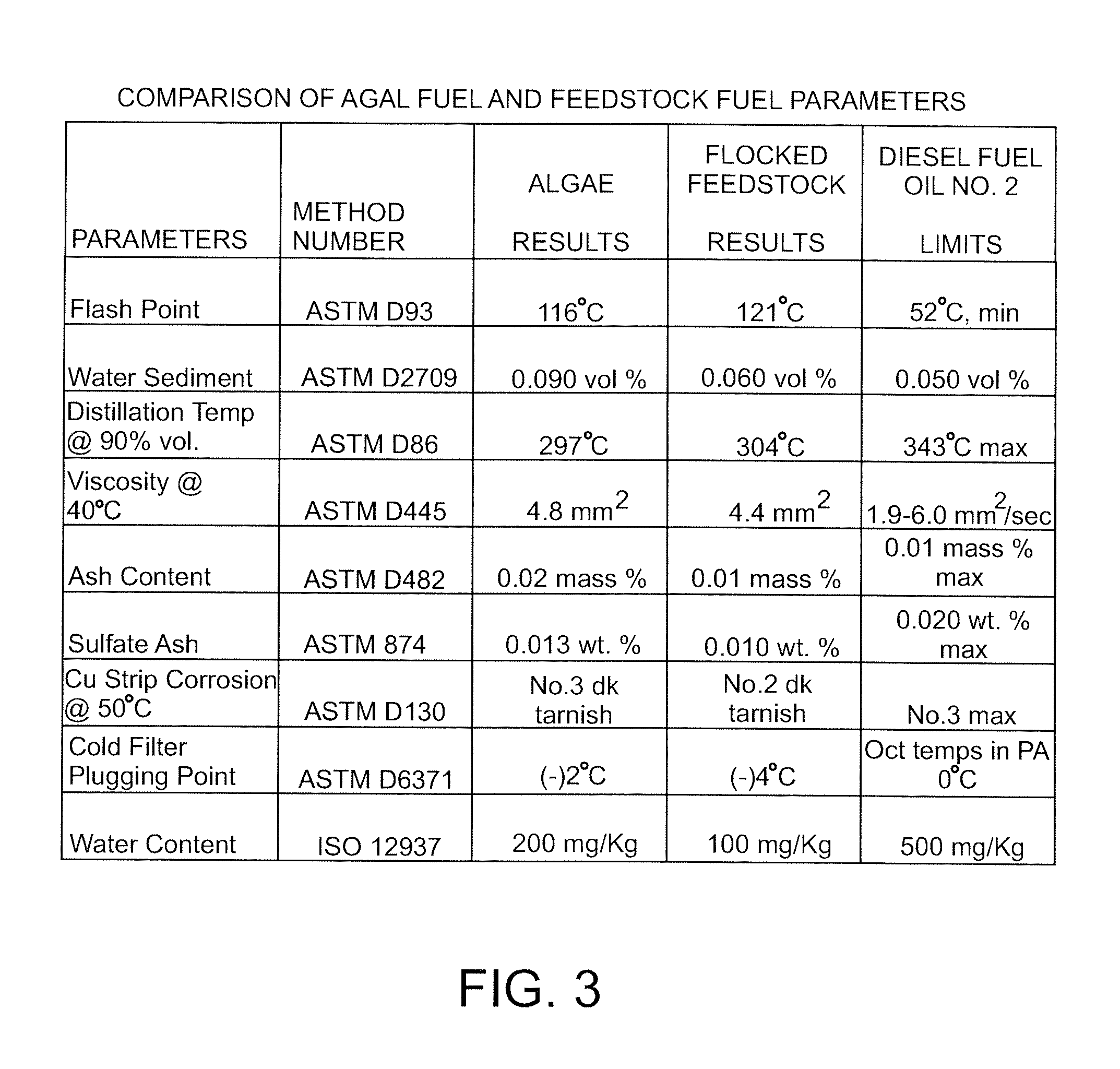
[0056]For this example, two feedstocks were run with the same catalyst. A first feedstock comprised 100% dried salt water algae. A second feedstock was comprised of a 25 / 75 mix (by weight) of dried salt water algae and flocked wood comprising 60% pine saw dust (⅜ in. particle size or less) and 40% FOG in the form of yellow grease. The flocked wood feedstock component was prepared in the same manner as example 1. Sixty (60) pounds of each feedstock was used. Thus, the first feedstock comprised sixty (60) pounds of algae and the second feedstock comprised thirty-six (36) pounds of saw dust and twenty-four (24) pounds of FOG.

[0057]The consumable catalyst used for this example was comprised (approximately) of 12% Kaolin, 28% zeolite, 28% silicon dioxide (amorphous), 28% aluminum oxide as Al(2)O(3), 2.5% aluminum phosphate and 1.5% rare earth elements. The amount of catalyst mixed with the 60 pounds of feedstock was 0.24 pounds. Thus, the catalyst content by weight was the same as in Exa...


PUM

PropertyMeasurementUnit
Lengthaaaaaaaaaa
Fractionaaaaaaaaaa
Fractionaaaaaaaaaa

Abstract

A biofuel production method, catalyst and system. The method may include combining a feedstock comprising a carbonaceous material with a consumable catalyst to produce a feedstock / catalyst mixture, and subjecting the feedstock / catalyst mixture to a vacuum pyrolytic gasification and liquefaction process to produce one or more biofuels. The catalyst includes effective amounts of various catalyst constituents, which may include some or all of kaolin, zeolite, amorphous silica, alumina aluminum phosphate and rare earth elements. The system may include apparatus for heating the feedstock / catalyst mixture under selected temperature and vacuum pressure conditions to produce a gaseous effluent comprising one or more hydrocarbon fractions, and additional distillation and condensation apparatus to produce one or more liquid and gaseous fuels.

Description

CROSS-REFERENCE TO RELATED APPLICATIONS[0001]The present application claims the benefit under 35 U.S.C. 119(e) of U.S. Provisional Patent Application No. 61 / 225,999, the entire contents of which are fully incorporated herein by this reference.BACKGROUND[0002]1. Field[0003]The present disclosure relates to the production of liquid and gaseous fuels from carbonaceous materials, and more particularly to a biofuel production technique that converts biomass into one or more biofuel output products that are primarily liquid fuel forms.[0004]2. Description of the Prior Art[0005]By way of background, various methods have been used to convert renewable biomass feed stocks into biofuels. A first category comprises standard gasification methods that produce gaseous fuels such as methane and syngas. A second category comprises biodiesel methods that produce liquid fuel from bio-oils through the chemical process of transesterification. A third category comprises the production of liquid ethanol ...

Claims


Application Information

Patent Timeline
IPC IPC(8): C10B57/12B01J29/06B01D5/00
CPCB01J29/06C10G2400/20C10B47/44C10B53/02C10G1/02C10G1/086C10L1/023C10L1/026C10L1/04C10L1/06C10L1/08C10L3/00Y02E50/13Y02E50/14Y02E50/32Y02T50/678C10G3/49C10G2300/1014C10G2300/1018C10G2300/4006C10G2300/4012C10G2300/4087C10G2400/02C10G2400/04C10G2400/08B01J2229/42Y02E50/10Y02E50/30Y02P20/145Y02P30/20
Inventor CHAMPAGNE, GARY E.
Owner CHAMPAGNE GARY E
Learn More