Nitride semiconductor laser device and wafer
a laser device and semiconductor technology, applied in semiconductor lasers, semiconductor/solid-state device details, optical beam sources, etc., can solve the problems of increasing cost and productivity, impractical for actual mass production, and reducing efficiency, so as to increase the noise reduction effect of high-frequency superposition circuit, reduce capacitance, and improve response
- Summary
- Abstract
- Description
- Claims
- Application Information
AI Technical Summary
Benefits of technology
Problems solved by technology
Method used
Image
Examples
first embodiment
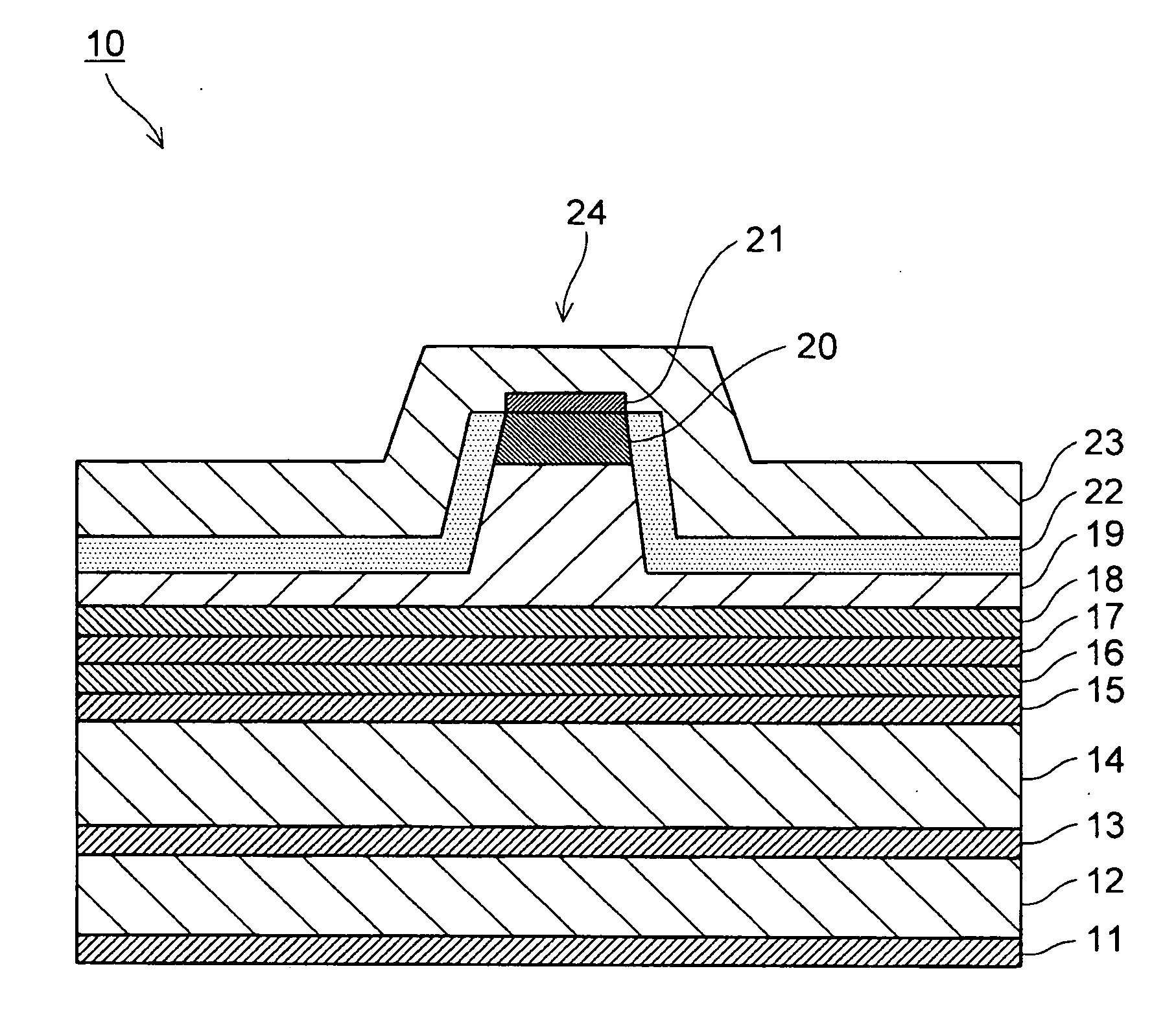
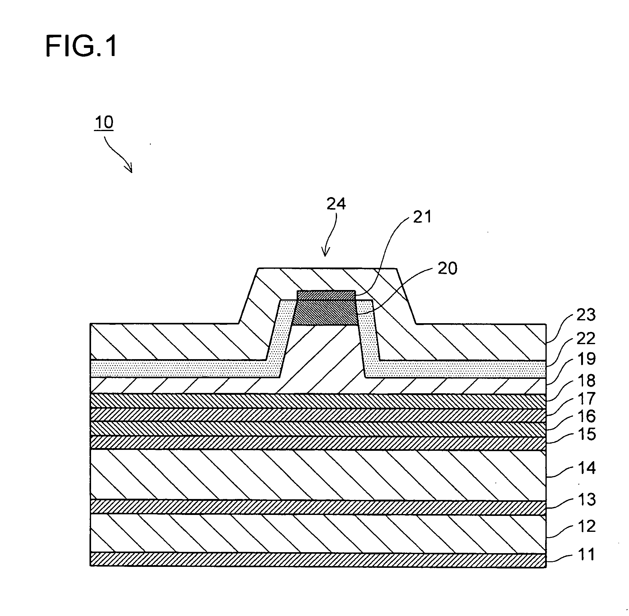
[0041]FIG. 1 is a sectional view of a nitride semiconductor laser device according to a first embodiment. The nitride semiconductor laser device denoted by 10 is built by stacking an n-type electrode 11, an n-type GaN substrate 12, an n-type GaN buffer layer 13, an n-type AlGaN cladding layer 14, an n-type GaN / InGaN light guiding layer 15, a non-doped GaN / InGaN active layer 16, a p-type AlGaN vaporization preventing layer 17, a p-type GaN or AlGaN interlayer 18, a p-type AlGaN cladding layer 19, a p-type GaN contact layer 20, a Pd contact electrode 21, a low dielectric constant insulating film 22, and a Ti / Au pad electrode 23.
[0042]The nitride semiconductor laser device 10 is manufactured by first growing, on the n-type GaN substrate 12, by metal organic chemical vapor deposition (hereinafter abbreviated as MOCVD), the n-type GaN buffer layer 13, the n-type AlGaN cladding layer 14, the n-type GaN / InGaN light guiding layer 15, the non-doped GaN / InGaN active layer 16, the p-type AlGaN...
second embodiment
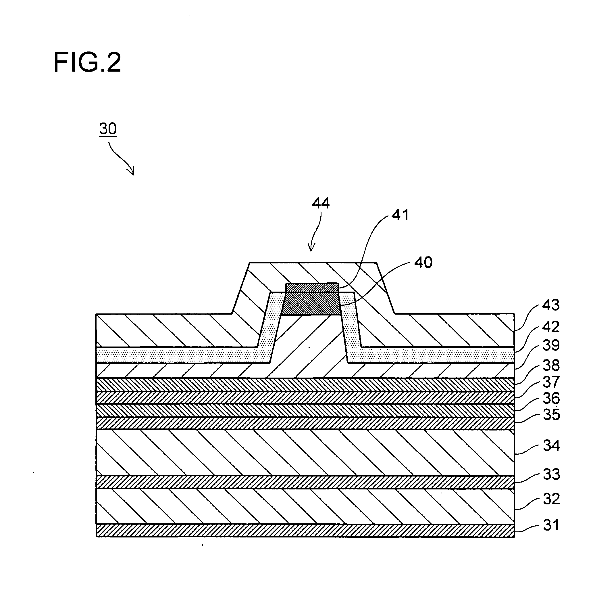
[0048]FIG. 2 is a sectional view of a nitride semiconductor laser device according to a second embodiment. The nitride semiconductor laser device denoted by 30 is built by stacking an n-type electrode 31, an n-type GaN substrate 32, an n-type GaN buffer layer 33, an n-type AlGaN cladding layer 34, an n-type GaN / InGaN light guiding layer 35, a non-doped GaN / InGaN active layer 36, a p-type GaN or AlGaN interlayer 37, a p-type AlGaN vaporization preventing layer 38, a p-type AlGaN cladding layer 39, a p-type GaN contact layer 40, a Pd contact electrode 41, a high dielectric constant insulating film 42, and a Ti / Au pad electrode 43.
[0049]The nitride semiconductor laser device 30 is manufactured by first growing, on the n-type GaN substrate 32, by metal organic chemical vapor deposition (hereinafter abbreviated as MOCVD), the n-type GaN buffer layer 33, the n-type AlGaN cladding layer 34, the n-type GaN / InGaN light guiding layer 35, the non-doped GaN / InGaN active layer 36, the p-type GaN...
third embodiment
[0055]A third embodiment of the present invention uses a processed substrate that is an n-type GaN substrate with grooves formed in a stripe pattern in its top face (epitaxy face). The processed substrate is manufactured by first forming an SiO2 film or the like on the top face of an n-type GaN substrate by sputtering evaporation to a thickness of 1 μm, and forming a stripe photoresist pattern by a common lithography process such that the photoresist pattern has a width of 5 μm at a resist opening and an interval (cycle) of 400 μm between the center of a stripe and the center of an adjacent stripe.
[0056]Next, the SiO2 film and the n-type GaN substrate are etched by dry etching such as reactive ion etching (RIE) technology to form grooves each having a depth of 5 μm and an opening width of 5 μm. The SiO2 film is then removed with the use of an etchant such as HF, to thereby obtain the processed substrate.
[0057]The deposition by evaporation of SiO2 is not limited to sputtering evapora...
PUM
 Abstract
Description
Claims
Application Information
 - R&D
- Intellectual Property
- Life Sciences
- Materials
- Tech Scout
- Unparalleled Data Quality
- Higher Quality Content
- 60% Fewer Hallucinations
Browse by: Latest US Patents, China's latest patents, Technical Efficacy Thesaurus, Application Domain, Technology Topic, Popular Technical Reports.
© 2025 PatSnap. All rights reserved.Legal|Privacy policy|Modern Slavery Act Transparency Statement|Sitemap|About US| Contact US: help@patsnap.com


