
Oligoaniline compound

Active Publication Date: 2010-09-16
NISSAN CHEM IND LTD
View PDF14 Cites 28 Cited by
  • Summary
  • Abstract
  • Description
  • Claims
  • Application Information

AI Technical Summary

Benefits of technology

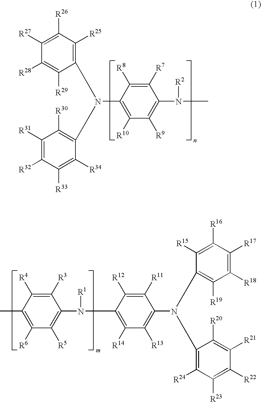
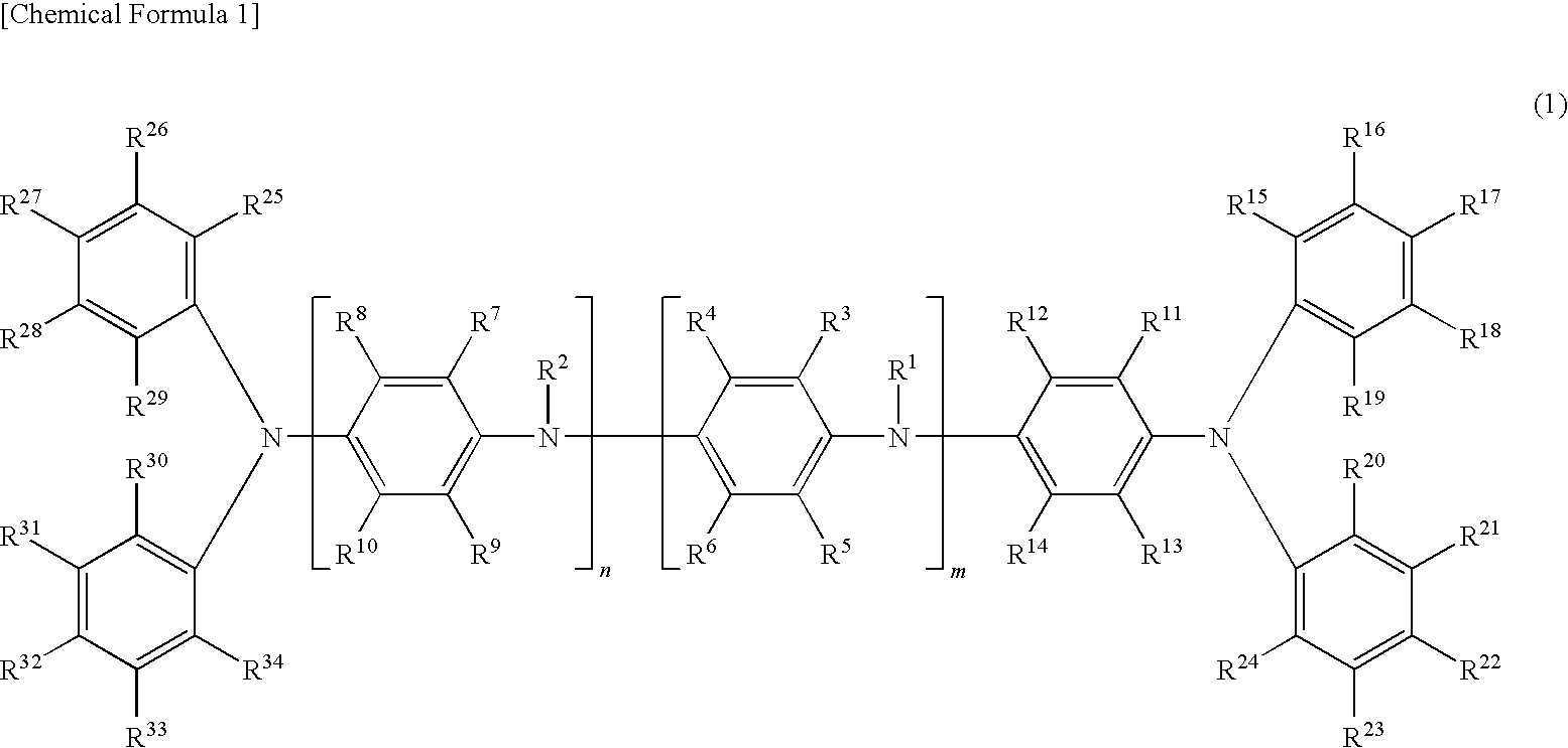
[0024]The oligoaniline compound according to the present invention has the triphenylamine structure and exhibits good conductivity owing to its high hopping mobility. Therefore, it gives rise to a thin film which also exhibits good conductivity. This thin film contributes to improved characteristic properties of the organic EL device containing it.
[0025]According to the present invention, the oligoaniline compound having the triphenylamine structure may be used in combination with a silane compound to form a thin film for the organic EL device. This thin film not only greatly extends the life of the organic EL device but also improves the luminance of the organic EL device.
[0026]Meanwhile, conductive polymers and conjugated polymers exhibit a high conductivity because they permit charges to move in the direction of the main chain of each molecule. For this reason, it is common practice to increase the number of minimum repeating units, thereby extending the main chain, in order to improve conductivity. This procedure is not employed in the present invention for the oligoaniline compound having the triphenylamine structure. Instead improvement in conductivity is achieved by activating the charge hopping movement between adjacent molecules.
[0027]The oligoaniline compound according to the present invention gives rise to a thin film which is superior in flatness and charge transportability. Because of these characteristic properties, the thin film will find use as the hole transport layer of solar cells, the electrode of fuel cells, the protective film for capacitor electrodes, and antistatic film.

Problems solved by technology

The low-molecular-weight oligomer compound intrinsically has such a low viscosity that it gives rise to a solution of ordinary organic solvent which presents difficulties in forming a highly uniform film by coating (such as spin coating, ink jet coating, and spray coating) and baking under various conditions owing to its narrow process margin.

Method used


Image

  • Oligoaniline compound
  • Oligoaniline compound
  • Oligoaniline compound

Examples


example 1

[1-1] Synthesis of Dibromophenyltetraaniline

[0174]

[0175]In a 500-mL Erlenmeyer flask were placed 20 g (41.19 mmol) of PTA and 300 mL of chloroform. The content was stirred by means of an ellipsoidal stirring chip. (PTA did not dissolve in chloroform but remained suspending.) In a 200-mL beaker was placed 39.72 g (82.38 mmol) of tetrabutylammonium tribromide (TBABr3), which was dissolved in 50 mL of chloroform added later. The resulting solution was added dropwise to the chloroform-PTA solution, and the mixture was stirred for 20 hours at room temperature in the air. Then, the chloroform-PTA solution was transferred to a 1000-mL separatory funnel and washed five times with 100 mL of saturated aqueous solution of sodium thiosulfate. After separation, the chloroform layer was transferred to a 500-mL Erlenmeyer flask and then dehydrated with 20 g of anhydrous magnesium sulfate. With the anhydrous magnesium sulfate removed by filtration, the chloroform solution was transferred to a 500-m...

example 2

[2-1] Synthesis of N,N-di-(4-biphenylyl)-benzylamine

[0188]

[0189]In a 100-mL three-neck flask were placed 80 mL of toluene, 42.0 mg (0.187 mmol) of palladium acetate, and an ellipsoidal stirring chip. The two outer necks were closed with septum caps and the center neck was provided with a reflux coiled condenser. To the top of the condenser was attached a three-way stopcock, to which is attached a balloon filled with nitrogen gas. The atmosphere in the flask was replaced three times by nitrogen gas supplied from the balloon with the help of a vacuum pump. Into the flask was injected 0.6 g (3 mmol) of tris-t-butylphosphine by means of a syringe, followed by stirring for five to ten minutes at room temperature. The flask was further charged with 2.04 mL (18.7 mmol) of benzylamine, 10.0 g (42.9 mmol) of 4-dibromophenyl, and 4.3 g (44.9 mmol) of sodium t-butoxide. With the flask placed on an oil bath, the solution therein was gradually heated to 120° C. with stirring. After 20 hours, the...

example 3

[3-1] Synthesis of 4-Bromodiphenylamine

[0201]

[0202]In a 1000-mL Erlenmeyer flask were placed 20 g (118.1 mmol) of diphenylamine, 500 mL of chloroform, and an ellipsoidal stirring chip. In a 500-mL beaker was placed 113.8 g (236.2 mmol) of tetrabutylammoniumtribromide (TBABr3), which was dissolved in 200 mL of chloroform added later. The resulting solution was added dropwise to the chloroform-diphenylamine solution, and the mixture was stirred for 20 hours at room temperature in the air. Then, the chloroform-diphenylamine solution was transferred to a 1000-mL separatory funnel and washed seven times with 100 mL of saturated aqueous solution of sodium thiosulfate. The organic layer was transferred to a 1000-mL Erlenmeyer flask and then dehydrated with 100 g of anhydrous magnesium sulfate. With the anhydrous magnesium sulfate removed by filtration, the chloroform solution was transferred to a 1000-mL eggplant-shaped flask and freed of chloroform by means of an evaporator. The resulting...


PUM

PropertyMeasurementUnit
Massaaaaaaaaaa
Efficiencyaaaaaaaaaa
Transport propertiesaaaaaaaaaa

Abstract

Any of the oligoaniline compounds with a triphenylamine structure represented by the formula (1) exhibits satisfactory light emitting efficiency and brightness performance when used in either an OLED device or a PLED device and is further satisfactory in the solubility in organic solvents so as to be applicable to various coating methods.(each of R1 and R2 independently is a hydrogen atom, an optionally substituted monovalent hydrocarbon group, t-butoxycarbonyl, etc.; each of R3 to R34 independently is a hydrogen atom, hydroxyl, silanol, thiol, carboxyl, a phosphoric group, a phosphoric ester group, ester, thioester, amido, nitro, an optionally substituted monovalent hydrocarbon group, etc.; and each of m and n is an integer of 1 or greater provided that they satisfy the relationship m+n≦20).

Description

TECHNICAL FIELD[0001]The present invention relates to an oligoaniline compound and, more particularly, to an oligoaniline compound having the triphenylamine structure, the use of this compound as a charge transport material, and a charge transport varnish containing this compound.BACKGROUND ART[0002]It has been reported that the low-molecular-weight organic electroluminescent (OLED for short hereinafter) device is provided with a copper phthalocyanine (CuPC) layer as the hole injection layer so as to improve the initial characteristics, such as reduced drive voltage and increased light-emitting efficiency, and to improve the life characteristics (Non-Patent Document 1: Applied Physics Letters, U.S., 1996, vol. 69, p. 2160-2162).[0003]It has also been reported that the organic electroluminescence (PLED for short hereinafter) device with a polymeric luminescent material produces the same effect as the OLED device does if it is provided with the hole transport layer in the form of thin...

Claims


Application Information

Patent Timeline
IPC IPC(8): H01B1/12C07C211/55C07C211/54
CPCC07C211/54C07C211/56C08G73/0266C09D5/24C09D179/02Y02E10/549H01L51/0059H01L51/5048H01L51/5052H01L51/5088H01L51/5092H01L51/0035H10K85/111H10K85/631H10K50/14H10K50/17H10K50/155H10K50/165H10K50/171H10K71/10
Inventor YAMADA, TOMOHISAYOSHIMOTO, TAKUJI
Owner NISSAN CHEM IND LTD
Learn More