
Method of manufacturing a composite, especially a bulletproof composite, and composite obtained

a technology of composite materials and composite materials, applied in weaving, looms, animal husbandry, etc., can solve the problems of reducing the kinetic energy associated with impact, elongating the yarns forming textile reinforcements until they break, and the delamination of shielding materials following impact cannot be eliminated

Inactive Publication Date: 2010-08-26
ENSAIT
View PDF6 Cites 16 Cited by
  • Summary
  • Abstract
  • Description
  • Claims
  • Application Information

AI Technical Summary

Benefits of technology

[0017]2.5D weaving designates the weaving technique which produces fabrics called “interlock warp” or 2.5D, which can be made on a conventional weaving loom and enabling the introduction of yarns in the thickness of multi-layer fabric. The fabric interlock warp is in the form of a multi-layer fabric whereof the binding between the superposed layers is ensured by warp yarns. The weaving technique utilised is that of multiwarp weaving on a warp and weft loom during which opening the shed is unidirectional, contrary to 3-dimensional weaving. Interlock fabrics can be woven on all types of weaving looms adapted to receive layers of warp yarns necessary for making said fabrics. The number of layers of warp yarns is a function of the number of shafts available on the loom and of the width connection of the selected weave. 2.5D fabrics are adapted for making thin structures as there are no inter-layer cavities such as in a three-dimensional fabric (3D). This arrangement optimises the quantity of polymer matrices and helps produce light composite materials.
[0060]Since incorporating the polymer matrix is easier to master because it takes place during weaving, its quantity is optimised. The applicant has accordingly developed a composite material used as a rear layer in a composite assembly for shielding having a surface mass of the order of 10% less than the surface mass of equivalent composite materials in terms of performance. This arrangement has considerable energy savings, especially for protection of aerial vehicles, and prevents wear on mechanical parts (shock absorbers, . . . ) of terrestrial vehicles.

Problems solved by technology

The face of the ceramic plate exposed to impact tends to fragment hard-cored ammunition of perforating bullets and reduces the kinetic energy associated with this impact.
However, at the binding points the waves are reflected and are superposed, causing elongation of the yarns forming the textile reinforcement until they break.
Resistance to delamination is primordial for shielding materials, especially in the case of multi-impact shots, since the integrity of their structure is threatened.
However, delamination of shielding materials following impact must not be eliminated.
Also, since the quality of the impregnation using these techniques is not satisfactory for composite materials of substantial thickness, of the order for example of 20-25 mm for composite materials forming the rear layer of the composite assemblies for shielding, several textile plies are then impregnated individually then stuck together.
It is however more difficult to control the stress placed on the weft yarns than on the warp yarns.

Method used


Image

  • Method of manufacturing a composite, especially a bulletproof composite, and composite obtained
  • Method of manufacturing a composite, especially a bulletproof composite, and composite obtained

Examples


Embodiment Construction

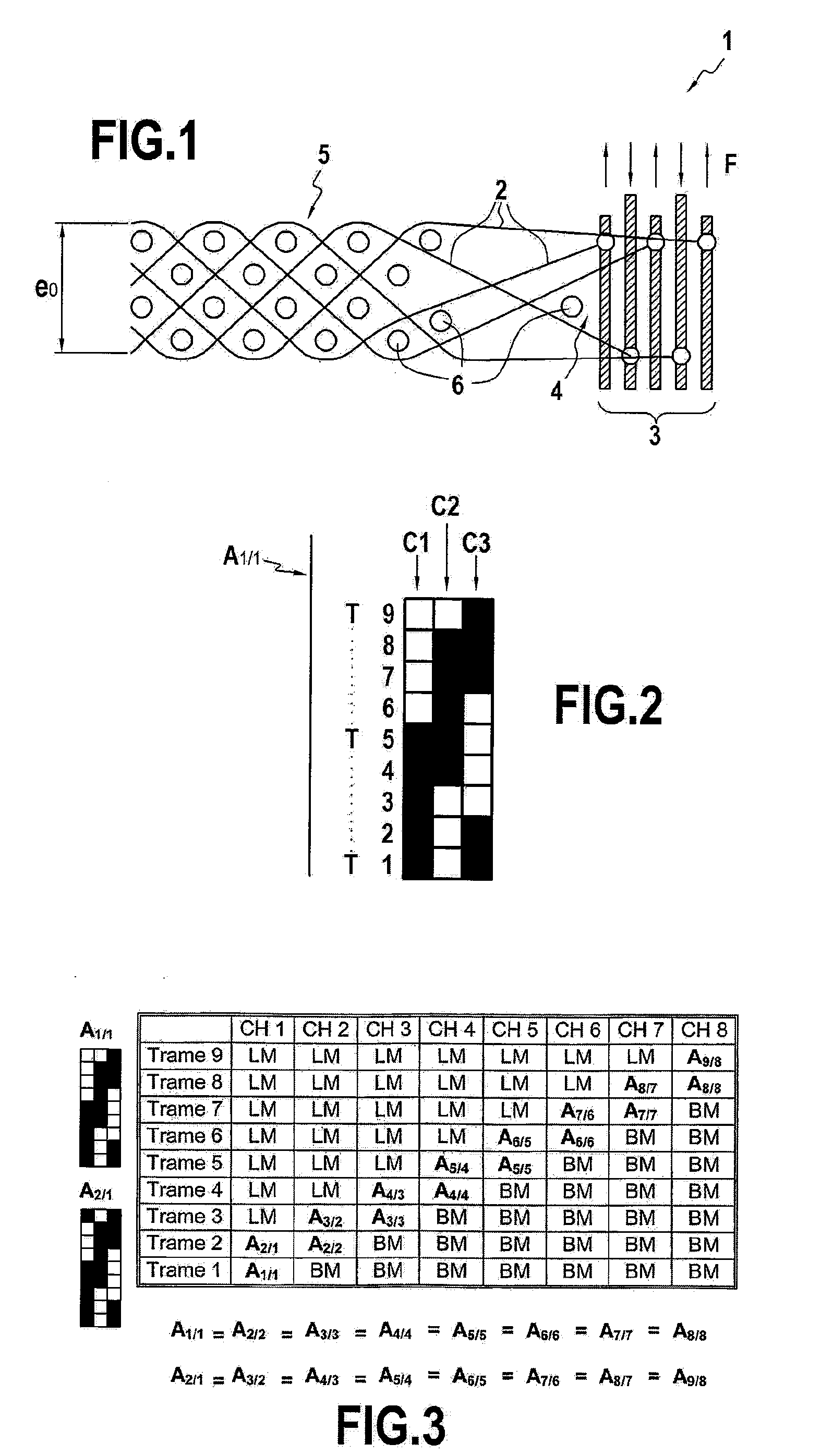
[0067]The weaving loom 1 represented partially in FIG. 1 manages five warp 2. During vertical movement F of the frames 3, supporting the healds in which the warp yarns are inserted, several warp 2 can be shifted upwards at the same time to form a single shed 4. The interlock fabric 5 is formed in this example of five layers 2 of warp yarns and weft yarns 6. These layers 2 are in turn connected to each other by chain yarns. The weft yarns 6 are inserted into the thickness e0 of the interlock fabric 5.

[0068]The base weaving pattern A1 / 1 shown in FIG. 2 is a diagonal 5-4 with a step number of 3. The step number is the offset from one weft pick to another. In general, the number of layers of chain yarns is equal to the number of blades available on a weaving loom divided by the width connection of the selected weave. The weaving loom utilised in this embodiment, not shown here, comprises 24 blades. The blades are the frames supporting the healds. The interlock fabric 7, obtained by usin...


PUM

PropertyMeasurementUnit
Fractionaaaaaaaaaa
Fractionaaaaaaaaaa
Forceaaaaaaaaaa

Abstract

The subject of the present invention is a method of manufacturing a composite (8) comprising a textile reinforcement (7) and a polymer matrix, especially a bulletproof composite. Said method characteristically comprises: a step of forming the textile reinforcement (7) by 2.5D weaving of first yarns with second yarns in a defined weave (A1 / 1), said second yarns being of a thermosetting polymer and said first yarns being high-performance yarns, so as to obtain an interlock fabric (7); and then a heat treatment during which said interlock fabric (7) is subjected to specified temperature and pressure conditions so as to melt said second yarns in order to form the polymer matrix, without impairing the first yarns.

Description

FIELD OF THE DISCLOSURE[0001]The present invention is in the technical field of composite materials for structural applications, and more particularly for bulletproof protection.BACKGROUND OF RELATED ART[0002]Ballistics distinguishes two types of impact, low-energy impact and high-energy impact. The kinetic energy developed by a given projectile is determined by the following equation: Ec=½ mv2 (Joules) where m and v correspond respectively to mass in Kg and velocity in m / s of said projectile.[0003]The low-energy impact energy corresponds to impacts caused by side arms ammunition and sporting guns utilising non-perforating bullets with a soft core, the calibres of which extend from around 0.22 inch to 0.44 inch. Structures mainly used against this type of impact are called soft protections, constructed from a succession of layers of fabric, UD (UniDirectional) or even nonwoven fabrics connected by seams in the shape of checkerboard, diamond or cross.[0004]The high-energy impact corr...

Claims


Application Information

Patent Timeline
IPC IPC(8): B32B27/34D03D15/00D03D49/50
CPCY10T428/27F41H5/0485Y10T428/249921
Inventor BOUSSU, FRANCOISBEGUS, VIRGINIE
Owner ENSAIT
Learn More