Scroll compressor

Inactive Publication Date: 2005-03-10
FUJITSU GENERAL LTD
View PDF0 Cites 32 Cited by
  • Summary
  • Abstract
  • Description
  • Claims
  • Application Information

AI Technical Summary

Benefits of technology

[0008] The present invention has been made to solve the above-described problems, and accordingly an object thereof is to provide a scroll compressor which can surely supply an optimum quantity of lubricating oil to a refrigerant compressing section and restrain a decrease in compression efficiency caused by gas leakage.
[0010] According to the invention of the first aspect, by making the throttle pin in a state in which restraint in the oil supply passage is lifted by the predetermined clearance (what is called free), unlike the conventional example, a fixing hole for fixing the throttle pin need not be provided. Also, there is no need for making the position of oil supply hole highly accurate, so that the fabrication cost can be reduced.
[0012] According to the invention of the second aspect, leakage of refrigerant from a gap between the end plate back surface of orbiting scroll and the thrust ring is eliminated, so that the capability is improved, and on the other hand, oil supply through this gap is also eliminated, so that the compression chamber can be lubricated by the oil supply in accordance with the present invention without a decrease in capability.
[0014] According to the invention of the third aspect, the fabrication cost of oil supply passage can be reduced. According to the invention of a fourth aspect, the end portion on the side opposite to the suction port of the transverse hole has a high pressure, so that the intrusion of refrigerant into the end portion on the side opposite to the suction port of the transverse hole through the gap with the closed shell can be prevented, and hence the quantity of supplied oil can be stabilized.
[0020] According to the inventions of the fifth to eighth aspects, the lubricating oil can be supplied to the suction chamber as possible as directly, and hence poor lubrication at the start time can be reduced.

Problems solved by technology

However, the scroll compressor having the aforementioned lubricating oil supply mechanism has problems described below.
In the scroll compressor described in Patent Document 1, the throttle pin for regulating the inflow quantity of lubricating oil is fixed to the fixed scroll, so that the position of a vertical hole for oil supply engaging with the fixed scroll must be designed with high accuracy, which increases the manufacturing cost.
Also, when accuracy necessary for positioning is required, a clearance between the vertical hole and the throttle pin becomes small, which poses a problem in that an adequate quantity of lubricating oil cannot be obtained.
When a nozzle is used, however, there arises a problem in that the hole is clogged with dirt and wear particles.
In this case, the refrigerant dissolved in the lubricating oil performs the inherent job, so that the quantity of refrigerant discharged to the refrigerating cycle decreases, which poses a problem of decreased capability.

Method used


Image

  • Scroll compressor
  • Scroll compressor
  • Scroll compressor

Examples


Embodiment Construction

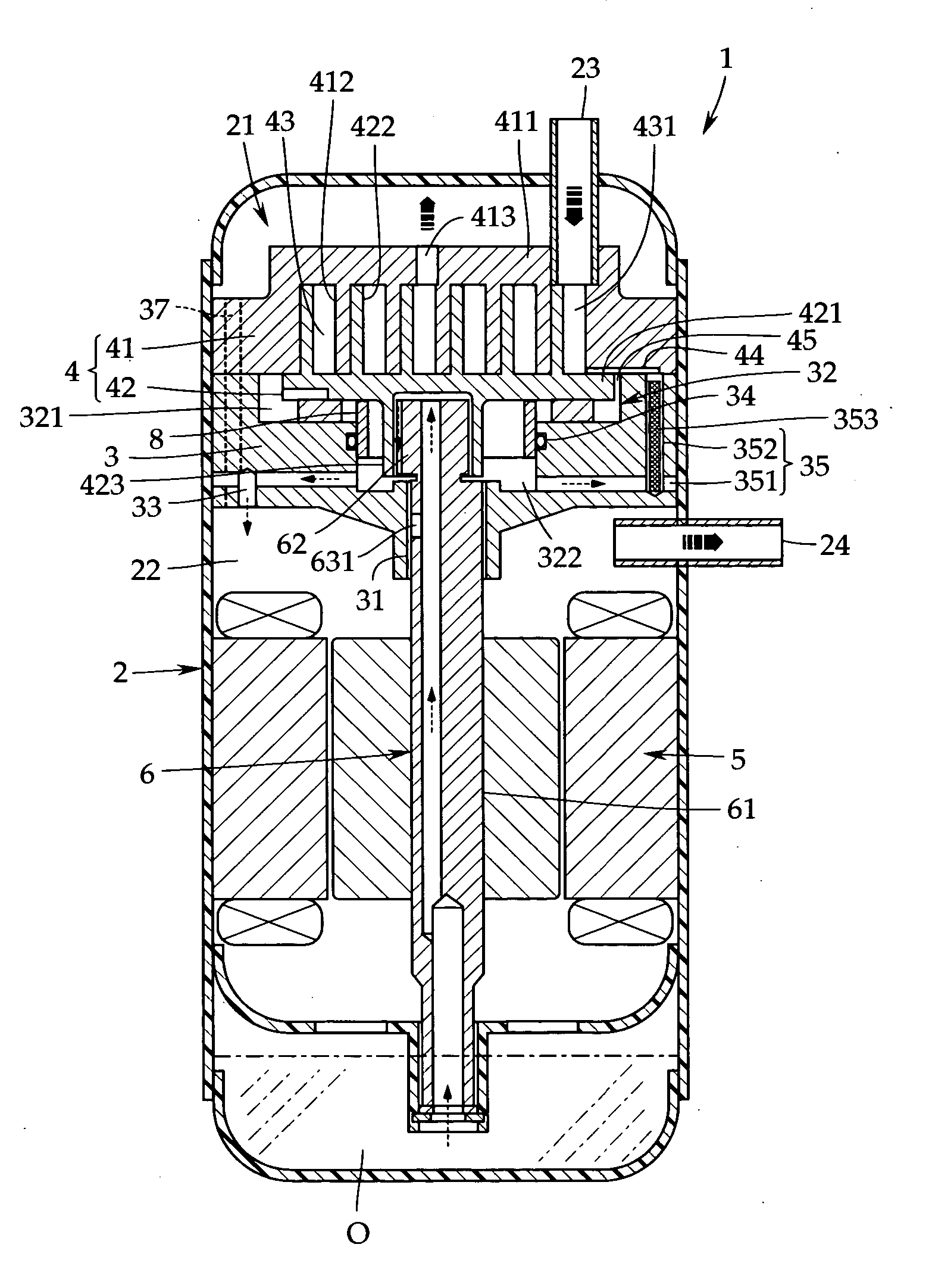
[0025] An embodiment of the present invention will now be described with reference to the accompanying drawings. In FIG. 1, a scroll compressor 1 consists of a vertically disposed cylindrical closed shell 2 having a discharge chamber 21 on the upper side and a motor chamber 22 on the lower side, which are divided with a main frame 3 held therebetween.

[0026] In the discharge chamber 21, a refrigerant compressing section 4 consisting of a fixed scroll 41 and an orbiting scroll 42 is contained, and in the motor room 22, a motor 5 for driving the refrigerant compressing section 4 and a rotational driving shaft 6 serving as an output shaft of the motor 5 are contained.

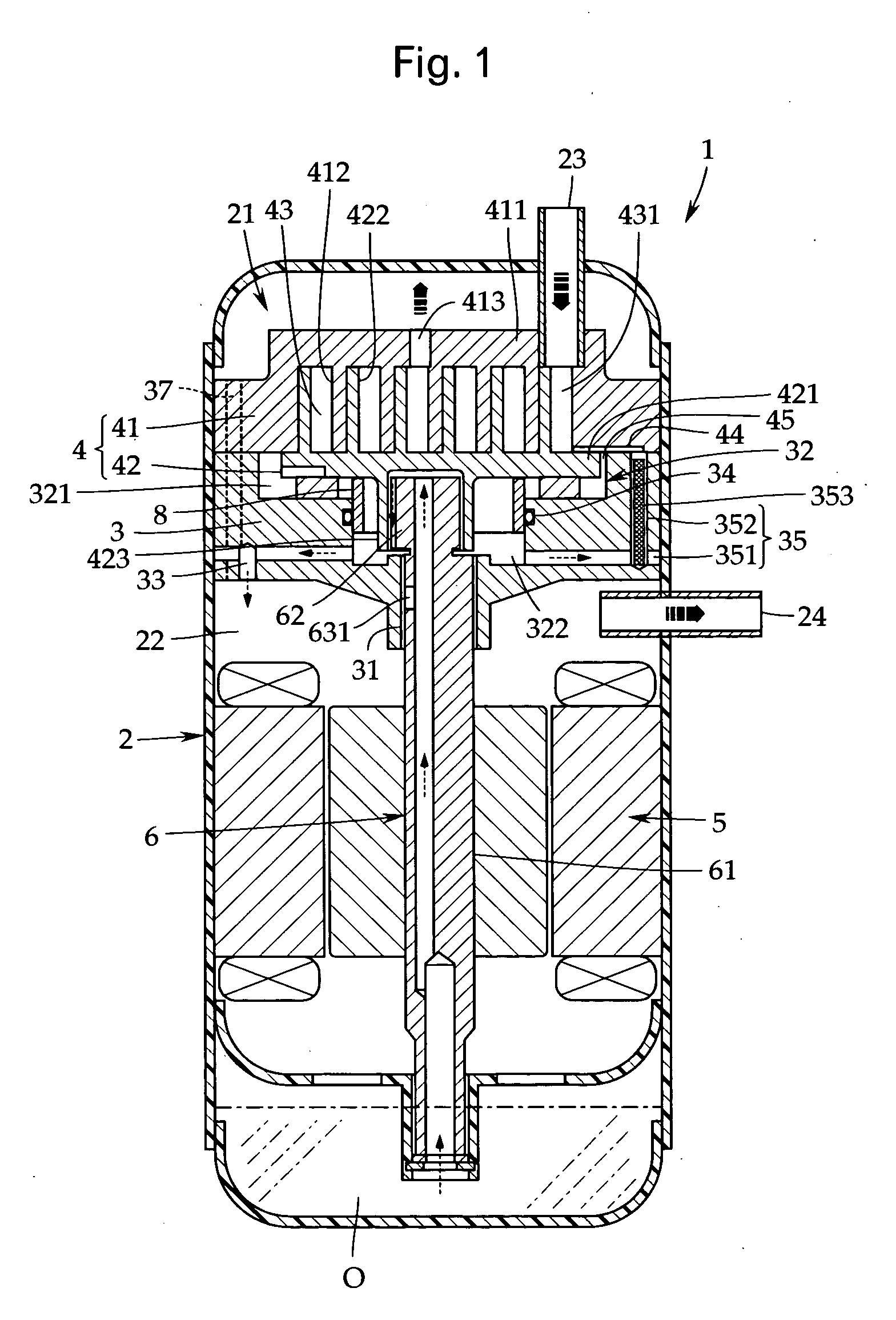
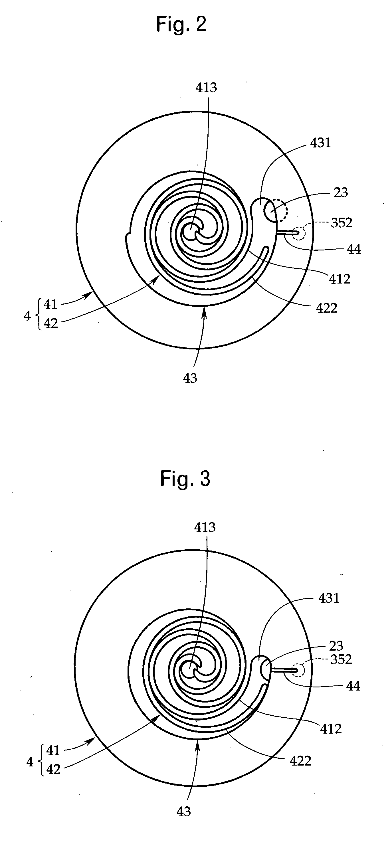
[0027] For the fixed scroll 41, a spiral scroll wrap 412 is integrally erected on one surface (lower surface in FIG. 1) of a disc-shaped end plate 411, and a discharge port 413 is provided in a substantially central portion of the end plate 411 to discharge a high-pressure refrigerant produced therein into the discharge c...


PUM


Abstract

There is provided a scroll compressor which can surely supply an optimum quantity of lubricating oil to a refrigerant compressing section and restrain a decrease in compression efficiency caused by gas leakage. An oil supply passage 35 whose discharge port is open to a joint surface of a main frame 3 and a fixed scroll 4 is provided, and a throttle pin 353 is inserted in the oil supply passage 35 with a predetermined clearance to regulate the inflow quantity of lubricating oil O. Also, a groove-shaped connecting portion is formed in the joint surface on the main frame side to connect the discharge port to a compression chamber 43.

Description

TECHNICAL FIELD [0001] The present invention relates to a scroll compressor used in a refrigerating cycle for an air conditioner or the like and, more particularly, to a scroll compressor in which a compression loss due to gas leakage in a refrigerant compressing section is reduced. BACKGROUND ART [0002] In a scroll compressor, a fixed scroll and an orbiting scroll having spiral scroll wraps erecting perpendicularly on an end plate are engaged with each other with the scroll wraps, and thereby a refrigerant compressing section forming a compression chamber (closed operation chamber) therein is provided. [0003] In the refrigerant compressing section, by rotating the orbiting scroll by a rotational driving shaft provided with a crankshaft, the crescent-shaped compression chamber formed by the scroll wraps is moved from the outside to the inside while the volume thereof is decreased. Thereby, a low-pressure refrigerant introduced to the inside is compressed into a high-pressure refrige...

Claims


Application Information

Patent Timeline
IPC IPC(8): F04C18/02F04C23/00F04C29/02
CPCF04C18/0215F04C18/0246F04C29/028F04C29/023F04C23/008F04C18/02
Inventor MOROZUMI, NAOYAFUJINO, MASAKITANAKA, JUNYANAKAZAWA, TAKAYOSHI
Owner FUJITSU GENERAL LTD
Why Eureka
Try Eureka