
Superhydrophobic nanotextured polymer and metal surfaces

Inactive Publication Date: 2010-01-28
ARIEL UNIV RES & DEV
View PDF13 Cites 38 Cited by
  • Summary
  • Abstract
  • Description
  • Claims
  • Application Information

AI Technical Summary

Benefits of technology

[0012]FIG. 4. shows SEM images of the random fractal-like interface composed of PVDF beads aggregates deposited on PE substrates (relief B

Problems solved by technology

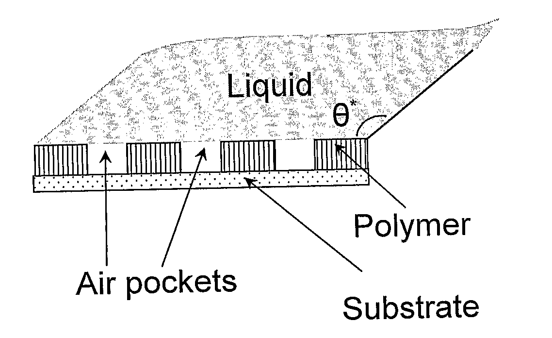
Although the wetting of textured surfaces have been theoretically studied, their practical utilization is disproportionately rare, and the lack of reproducible experimental data in the field is conspicuous [de Gennes P. G. et al.
Practical needs of hydrophobic surfaces are not satisfied, particularly in cases when the surface should comprise objects made of inherently hydrophilic materials.
In spite of significant experimental and theoretical efforts, a reproducible inexpensive manufacture of superhydrophobic surfaces is not available.
However, the applied layer is not always stable, and some applications do not allow applying such layers of chemicals.

Method used


Image

  • Superhydrophobic nanotextured polymer and metal surfaces
  • Superhydrophobic nanotextured polymer and metal surfaces
  • Superhydrophobic nanotextured polymer and metal surfaces

Examples


example 1

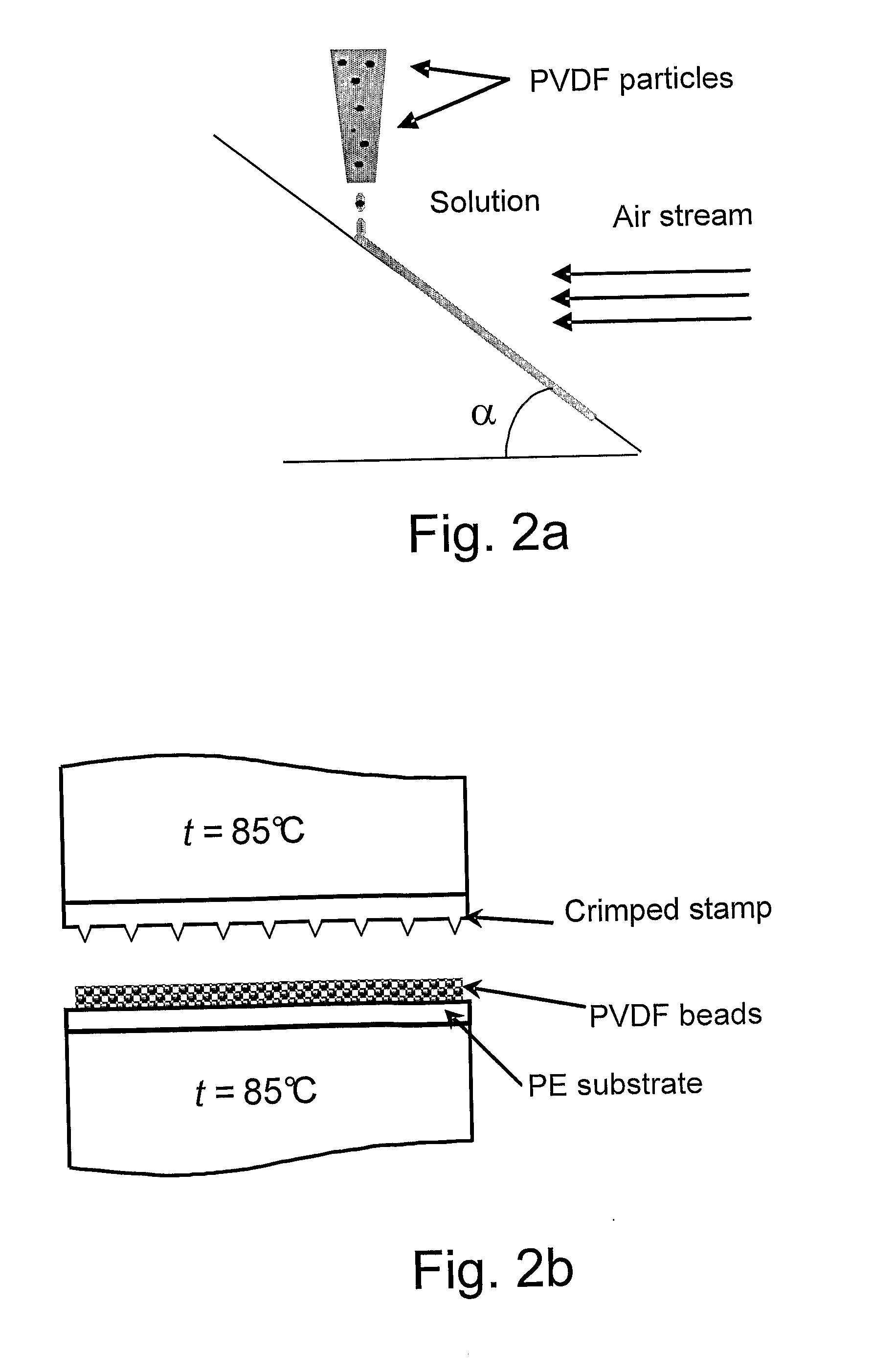
[0027]Highly hydrophobic polymer surfaces were obtained (FIG. 2a-b). Tilted base substrates were coated with chlorinated solvents-based solutions comprising polycarbonate and PVDF beads. Polycarbonate is soluble in the chlorinated solvents, whereas PVDF is not, thus a suspension was formed and dripped on the substrates as depicted in FIG. 2a, e.g. quartz glass substrate, and dried with a room temperature air current. The structure of the dry film studied by means of scanning electron microscopy (SEM) shows interconnected colloidal arrays (ICA), such as presented in FIG. 3a-b. These arrays are micro-scaled aggregates consisting of PVDF particles embedded in PC that filled the porosity between PVDF beads. The most frequent size of these aggregates was determined as 3-10 μm. The aggregates incorporate 104-106 PVDF nanoparticles. The relief displayed in FIG. 3 is mentioned further as Relief A.

[0028]At the first stage solutions containing 2-5 wt % of PC dissolved in chloroform were prepa...

example 2

[0029]A layer of PVDF beads in powder form has been spread at the surface of the low density polyethylene (PE) substrate (see FIG. 2b). Then the sandwich has been exposed to hot pressing with a randomly riffled stamp. The PE has been softened under the pressing and traps single PVDF particles (which are still solid under the pressing temperature) and globular aggregates were formed comprising PVDF beads. The aggregates, composed of nano-scaled beads frozen in the PE matrix, formed highly developed interface photographed in FIG. 4a-b. This random pseudo-fractal surface is mentioned below as Relief B. Pressed stamp indentations form “channels” important for increasing the hydrophobicity. Hot pressing was carried out under t=85° C. The characteristic distance between indentations of the riffled stamp was 100 μm, the depth of the indentations was 20 μm.

example 3

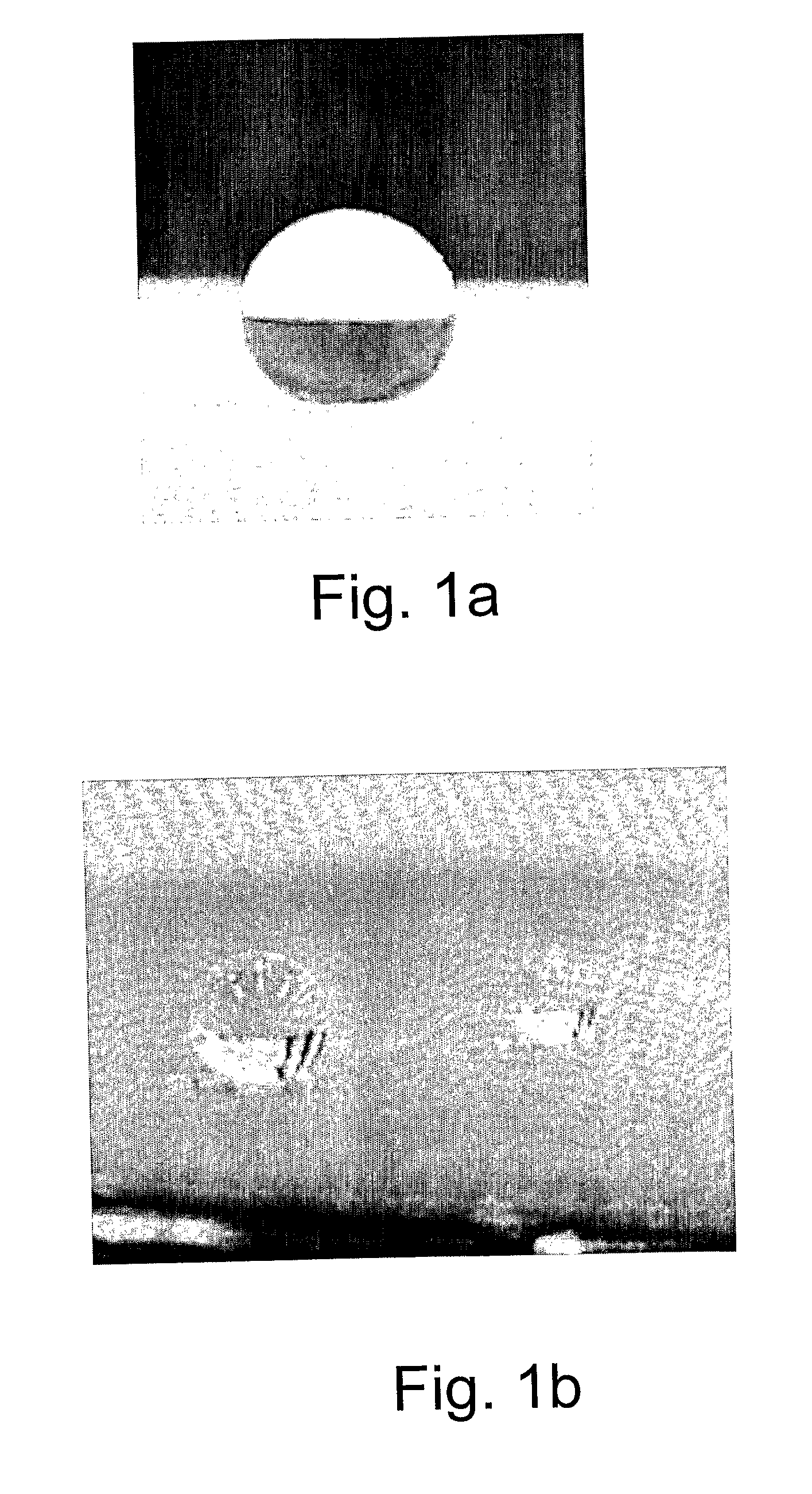
[0030]At the next stage, Reliefs A and B were coated with 360 Å gold films by a sputtering procedure in argon atmosphere. Then double distilled water droplets were dripped carefully on the coated templates. The volume of the droplets was 2-5 μl. Apparent contact angles are summarized in Table 1.

TABLE 1ACA values of the textured surfacesGold coatedGold coatedRelief Arelief ARelief Brelief BMeasured95 ± 5°95 ± 5°160 ± 5°150 ± 5°ACA


PUM

PropertyMeasurementUnit
Lengthaaaaaaaaaa
Lengthaaaaaaaaaa
Lengthaaaaaaaaaa

Abstract

A method of manufacturing a multiscale (hierarchical) superhydrophobic surface is provided. The method includes texturing a polymer surface at three size scales, in a fractal-like or pseudo-fractal-like manner, the lowest scale being nanoscale and the highest microscale. The hydrophobic polymer surface may be converted to hydrophobic metal surface by subsequent deposition of a metal layer onto the polymer surface.

Description

FIELD OF THE INVENTION [0001]The present invention relates to superhydrophobic polymer or metal surfaces, textured at three size scales, in a fractal-like or pseudo-fractal-like manner, the lowest scale being nanoscale.BACKGROUND OF THE INVENTION [0002]Although the wetting of textured surfaces have been theoretically studied, their practical utilization is disproportionately rare, and the lack of reproducible experimental data in the field is conspicuous [de Gennes P. G. et al.: Capillarity and Wetting Phenomena, Springer, Berlin, 2003; Lafuma, A.& Quéré, D.: Nature Materials 2 (2003) 457-60].[0003]Highly hydrophobic surfaces are needed in many important applications, such as in manufacturing water-repellant textile, in constructing fuel cells, in batteries for membranes non-wetted under storage, desalination membranes, antenna coatings, etc. The phenomenon of superhydrophobi-city, i.e. the situation when apparent contact angle (ACA) becomes close to 180°, was reported recently by d...

Claims


Application Information

Patent Timeline
IPC IPC(8): B32B3/10B05D3/12
CPCB05D1/42B05D5/067Y10T428/24612C23C14/205B05D5/08B05D3/007B05D5/04C09D5/00C09D127/16C09D169/00
Inventor BORMASHENKO, EDWARDBORMASHENKO, YELENAVAIMAN, GENESTEIN, TAMIR
Owner ARIEL UNIV RES & DEV
Learn More