
Robot Position Calibration Tool (RPCT)

Inactive Publication Date: 2009-10-15
ASML HLDG NV
View PDF24 Cites 31 Cited by
  • Summary
  • Abstract
  • Description
  • Claims
  • Application Information

AI Technical Summary

Benefits of technology

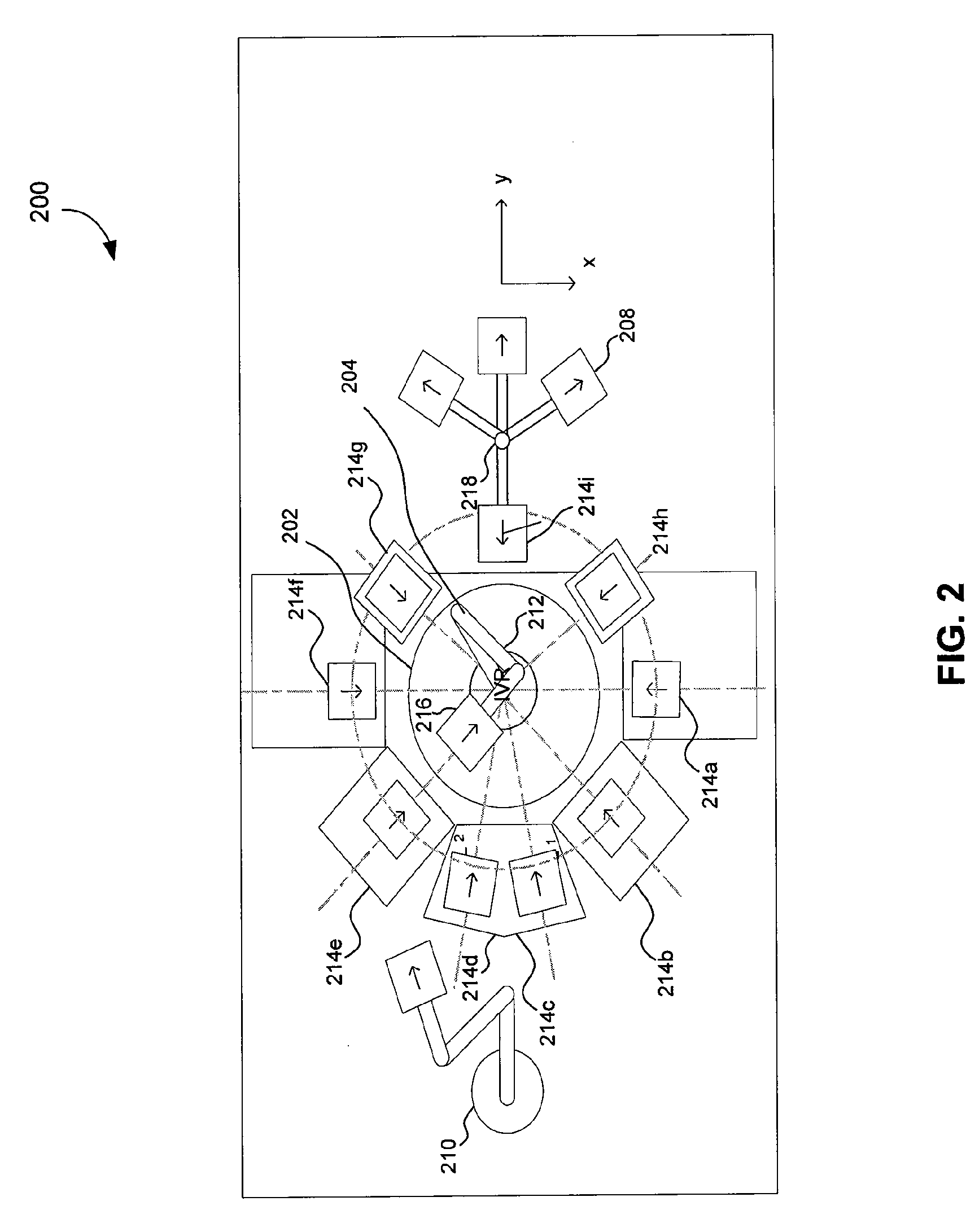
[0009]Therefore, what is needed is a system and method that fully automates in-vacuum robot calibration with minimum impact on the system in terms of particle generation or long term outgassing, that can produce a calibration result that minimizes repeated particle generation due to misalignment during reticle transfer, thereby substantially obviating the drawbacks of the conventional systems. What is also needed is a system and method to perform faster calibrations with minimum or no sensors inside vacuum.
[0011]Additionally, or alternatively, the vectorial distance (e.g., angular, linear or other) moved and the direction of movement of the RPCT, can be calculated by one or more sensors mounted on to the robot. Such sensors present on the robot may be hermetically sealed to avoid outgassing issues, thereby further reducing chances of defects in the final manufactured features on the / a wafer due to extraneous outgassing. Such sensors can be, for example, optical distance measurement sensors, or capacitance gauges.
[0012]In another embodiment, there is provided a method comprising exemplary steps for: moving an RPCT residing on an in-vacuum robot to record a first distance reading for a sensor on the robot, after the robot has moved a certain distance, recording a second distance reading, determining how much the RPCT has moved in-plane (e.g., in an x, y, and Rz co-ordinate system), determining a difference (offset) between the first and the second distance reading, determining based on the difference, whether the robot is aligned within acceptable limits with respect to a transfer station corresponding to a hand-off position, and storing a final robot hand-off position for future calibrations, thereby minimizing slippage of the RPCT (or any other type of a payload) during a transfer to a kinematic mount of the transfer station.

Problems solved by technology

Particles in lithographic systems are not desirable as they can alter the pattern being imprinted on the substrate and reduce effective productivity of the tool.
Alternatively, conventional systems that use optical alignment methods use an excessive number of sensors built-in to the robot arm and / or other parts of the lithographic apparatus to align and calibrate the robot.
All of the above-mentioned calibration techniques are undesirable, especially when a low level of particle generation (caused, for example, by contact between an end effector of the robot and a reference surface / transfer station, and slippage resulting from misaligned robot and a reference structure / transfer station), as in Extreme Ultra-Violet (EUV) tools, is desired.
Such techniques are also time consuming and limited by their choice of materials within a vacuum environment.
For example, human verification is not very accurate and is inconsistent.
In addition, human access to the vacuum chamber is not always possible, and even if access were possible, the access would lead to introduction of undesirable foreign particles in the vacuum chamber, which may cause erroneous / defective manufacturing.
Inaccurate alignment can also lead to slippage of a payload, further causing particle generation in the vacuum chamber.
Further, due to manufacturing and built-in machine tolerance and resolution limits, it is not possible to have a robot pre-programmed for accurate alignment before the lithography apparatus is assembled.
Various techniques that touch the end-effector to a predefined calibration surface require torque force sensors, which increase complexity and payload of the in-vacuum robot.
Physical contact between the end-effector and the calibration surface will cause undesirable particle generation.
Further, having additional sensors such as optical alignment inside the vacuum chamber leads to more molecular outgassing in to the vacuum environment that can damage the optics of the lithography apparatus.
Strict outgassing requirements also limit the choice of sensor materials, thereby increasing overall manufacturing costs.

Method used


Image

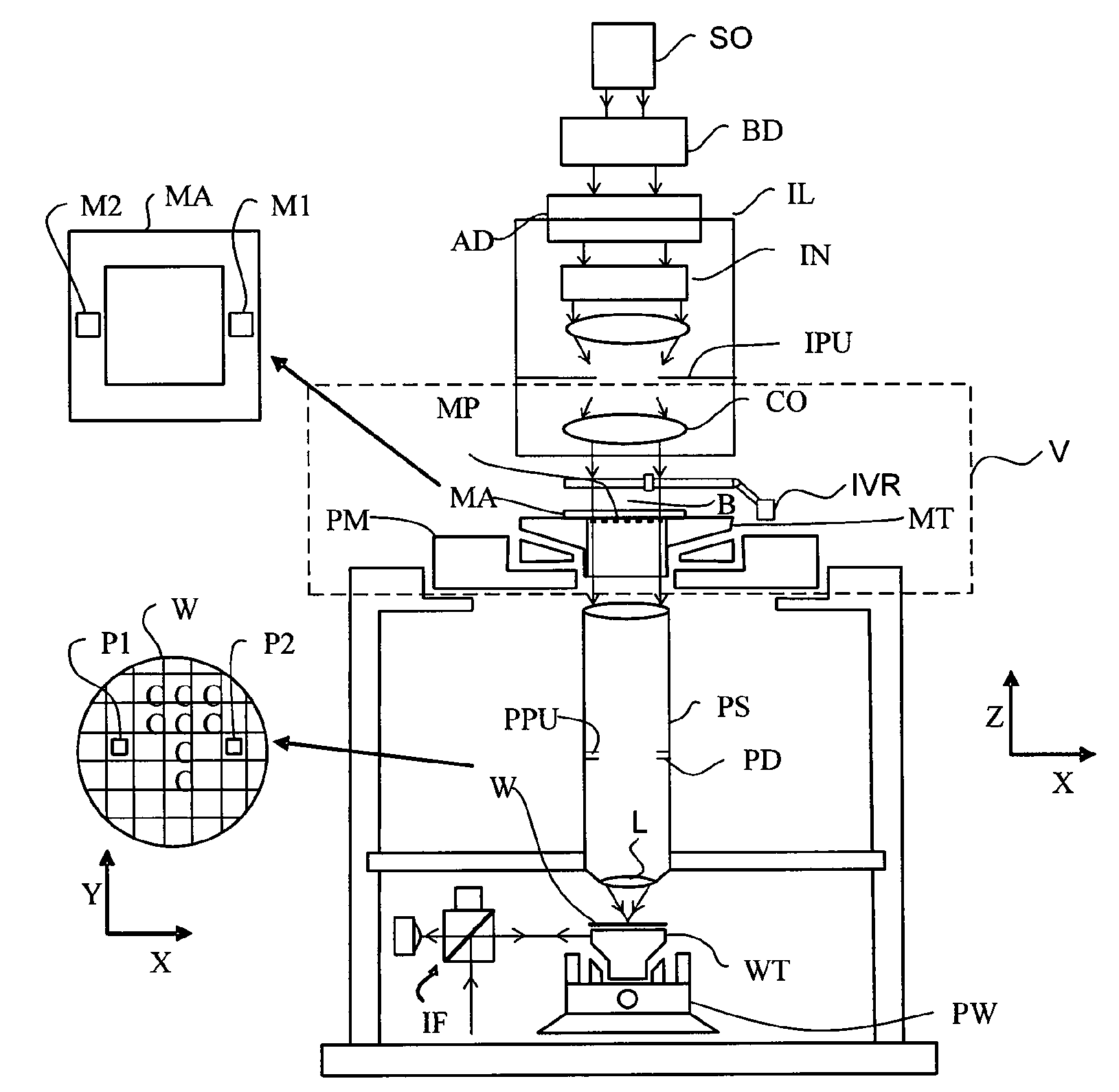
  • Robot Position Calibration Tool (RPCT)
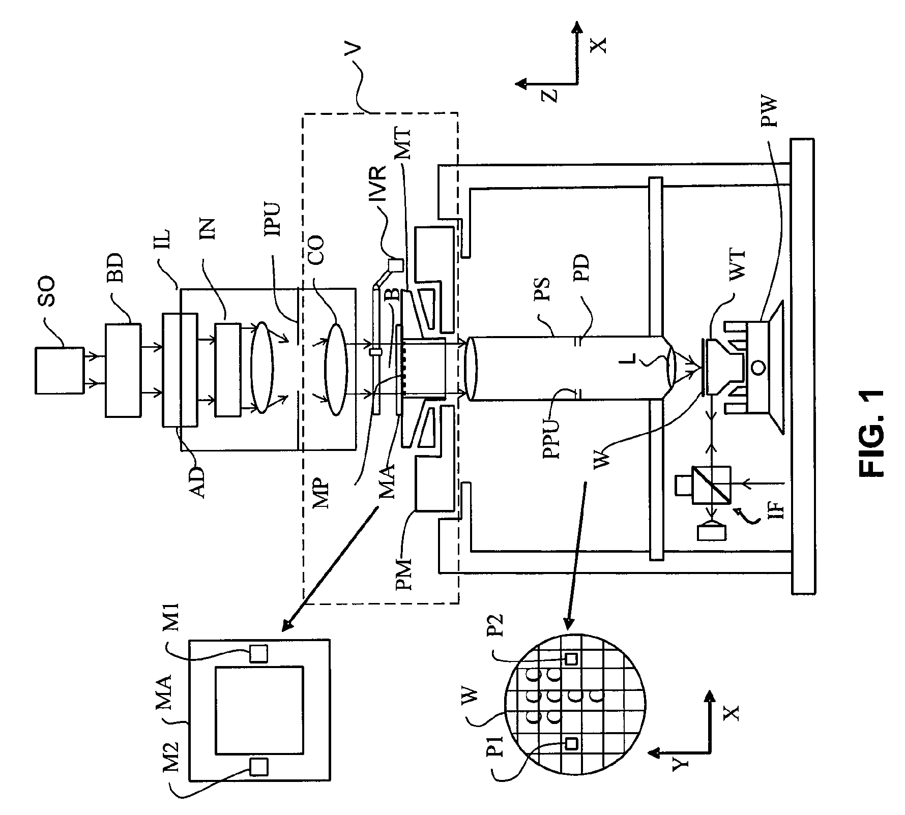
  • Robot Position Calibration Tool (RPCT)
  • Robot Position Calibration Tool (RPCT)

Examples


Embodiment Construction

[0028]This specification discloses one or more embodiments that incorporate the features of this invention. The disclosed embodiment(s) merely exemplify the invention. The scope of the invention is not limited to the disclosed embodiment(s). The invention is defined by the claims appended hereto.

[0029]The embodiment(s) described, and references in the specification to “one embodiment”, “an embodiment”, “an example embodiment”, etc., indicate that the embodiment(s) described may include a particular feature, structure, or characteristic, but every embodiment may not necessarily include the particular feature, structure, or characteristic. Moreover, such phrases are not necessarily referring to the same embodiment. Further, when a particular feature, structure, or characteristic is described in connection with an embodiment, it is understood that it is within the knowledge of one skilled in the art to effect such feature, structure, or characteristic in connection with other embodimen...


PUM


Abstract

A Robot Position Calibration Tool (RPCT) is used to accurately calibrate a robot position for a reticle hand-off to a transfer station in a lithography tool with minimized particle generation and outgassing. Method(s), system(s) and computer program product(s) are described to calibrate the robot with minimal sensor usage and minimal slippage of a payload leading to minimized particle generation and outgassing inside a vacuum chamber of a lithography tool.

Description

CROSS REFERENCE TO RELATED APPLICATIONS[0001]This application claims priority to U.S. Provisional Application No. 61 / 043,526, filed Apr. 9, 2008, which is incorporated by reference herein in its entirety.BACKGROUND[0002]1. Field of the Invention[0003]The present invention relates to an automated robot position calibration tool in a vacuum chamber of a lithography apparatus.[0004]2. Related Art[0005]A lithographic apparatus is a machine that applies a desired pattern onto a substrate or part of a substrate. A lithographic apparatus can be used, for example, in the manufacture of flat panel displays, integrated circuits (ICs) and other devices involving fine structures. In a lithographic apparatus, a robot (interchangeably referred to as “in-vacuum robot” herein) is used to place a reticle inside a vacuum chamber of the lithographic apparatus. To effectively transfer a reticle, the in-vacuum robot has to be accurately calibrated with respect to one or more transfer stations / hand-off p...

Claims


Application Information

Patent Timeline
IPC IPC(8): G06F19/00
CPCB25J9/1692G05B2219/40623G05B2219/39033
Inventor HARROLD, GEORGE HILARYJOHNSON, RICHARD JOHN
Owner ASML HLDG NV
Learn More