
Information storage apparatus

a technology of information storage and information storage, which is applied in the field of information storage apparatus, can solve the problems of flying height, serious influence, and inability to ensure stable activation, and achieve the effect of accurate flying height measurement, and reducing the time required for calibration

Inactive Publication Date: 2007-06-14
FUJITSU LTD
View PDF9 Cites 29 Cited by
  • Summary
  • Abstract
  • Description
  • Claims
  • Application Information

AI Technical Summary

Benefits of technology

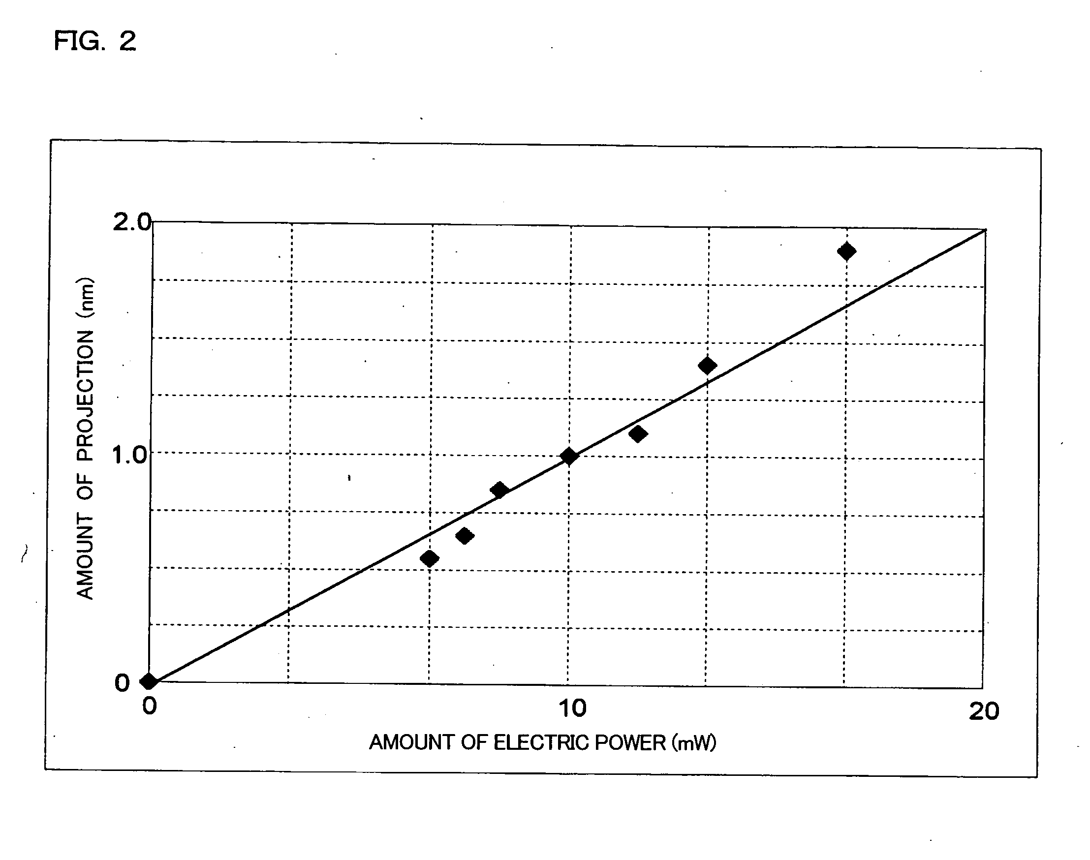
The present invention provides a power-saving information storage apparatus that can quickly perform calibration and be activated in a short time by determining the accurate flying height of a magnetic head. It also provides an information storage apparatus with a magnetic head that is durable and prevents plastic deformation of the magnetic pole end. The apparatus includes a magnetic head with a controllable magnetic pole end, a recording medium with a protrusion for measuring flying height, and a flying-height adjustment controller that adjusts the flying height of the magnetic head by controlling the amount of projection of the magnetic pole end. The apparatus prevents magnetic pole end from plastic deformation and adhering to the recording medium surface, resulting in high durability of the magnetic head.

Problems solved by technology

Although mobile apparatuses are useful in that they can be carried and used at different locations or while moving, there are disadvantages in that they are easily influenced by the operating environment, such as air pressure and temperature variation, and stable activation cannot be ensured.
Thus, the variation in the operating environment exerts a serious influence on the stability of the flying height of the magnetic head (causes variation in the flying height).
However, battery life is reduced since a considerably long time and large power consumption are required for the calibration for the calibration.
However, in practice, the flying height differs for each product due to differences in component accuracy and assembly accuracy between the products.
However, as described above, there are problems that it takes a long time to activate the apparatus since a relatively long time is required for the calibration and a large amount of power is consumed.
However, since the surface of the recording medium generally has grooves (texture) for preventing the magnetic head from adhering thereto and the measurement of the flying height is influenced by the roughness of the texture, the reliability of the measurement of the flying height is low and it is difficult to obtain the accurate flying height.
Accordingly, particularly in recent years when there have been increasing demands for large capacity recording media, a risk that the magnetic head will adhere to the surface of the recording medium has been increased.
Therefore, it is extremely difficult to cause the magnetic pole end of the magnetic head to come into contact with the surface of the recording medium and determine the accurate flying height of the magnetic head on the basis of the amount of projection of the magnetic pole end at that time.
On the contrary, since the flying height of the magnetic head tends to be increased when the air pressure is high or the temperature is low, there is a possibility that the flying height of the magnetic head may be too large when the magnetic head is loaded to the position above the recording medium.
When the flying height of the magnetic head is large, the magnetic pole end, of course, must be projected by a large amount and the calibration takes a long time.
In addition, there is a risk that the magnetic pole end cannot project long enough to come into contact with the recording medium surface.
In addition, if the magnetic pole end is projected by a very large amount, there is a risk that the projecting portion will deform plastically and the magnetic pole end cannot return to the initial position even when the heater is turned off.

Method used


Image

  • Information storage apparatus
  • Information storage apparatus
  • Information storage apparatus

Examples


first embodiment

[0070] Next, a calibration method according to the present invention will be described below.

[0071] In the first embodiment, the information storage apparatus according to the present invention is applied to a mobile apparatus.

[0072]FIG. 7 is a flowchart illustrating a process for calibrating the magnetic head flying height according to the present embodiment.

[0073] First, when the power of the information storage apparatus is turned on, a command for starting the calibration of the magnetic head 21 is executed (S101). Then, electric power is applied to the heating device 19 to heat the thin-film magnetic head element 10 so that the magnetic pole end 40 of the recording and reproducing elements 41 and 42 is deformed so as to project (S102). Then, the flying-height adjustment controller in the CPU checks a signal transmitted from the magnetic head 21 (S103), and it is determined whether or not the projection of the magnetic pole end 40 is in contact with the bump 31 formed on the r...

second embodiment

[0079] Next, a calibration method according to the present invention will be described below.

[0080] In the second embodiment, the information storage apparatus according to the present invention is applied to a non-mobile apparatus.

[0081]FIG. 9 is a flowchart illustrating a process for calibrating the magnetic head flying height according to the present embodiment.

[0082] First, before the information storage apparatus is shipped, a command for starting the calibration of the magnetic head 21 is executed (S201). Then, electric power is applied to the heating device 19 to heat the thin-film magnetic head element 10 so that the magnetic pole end 40 of the recording and reproducing elements 41 and 42 is deformed so as to project (S202). Then, the flying-height adjustment controller in the CPU checks a signal transmitted from the magnetic head 21 (S203), and it is determined whether or not the projection of the magnetic pole end 40 is in contact with the bump 31 formed on the recording...


PUM

PropertyMeasurementUnit
flying heightaaaaaaaaaa
electric poweraaaaaaaaaa

Abstract

An information storage apparatus includes a magnetic head having a magnetic pole end that is controllable so as to project, a recording medium for recording and / or reproducing data, a protrusion provided on a surface of the recording medium, the protrusion being used for measuring a flying height of the magnetic head, and a flying-height adjustment controller that adjusts the flying height of the magnetic head by controlling the amount of projection of the magnetic pole end of the magnetic head on the basis of the amount of projection obtained when the magnetic pole end of the magnetic head comes into contact with the protrusion.

Description

BACKGROUND OF THE INVENTION [0001] 1. Field of the Invention [0002] The present invention relates to an information storage apparatus that includes a magnetic head having a thin-film magnetic head element and a high-density recording medium and that records and / or reproduces data using the magnetic head. [0003] 2. Description of the Related Art [0004] Recently, there have been demands for small information storage apparatuses with large storage capacities, and magnetic heads having thin-film magnetic head elements that are small and capable of recording and / or reproducing data on recording media with high density have been used to satisfy such a demand. Such a magnetic head is mainly of a combined type including a recording element and a magnetoresistive (MR) element. [0005]FIG. 10 is an enlarged sectional view illustrating a part of a known thin-film magnetic head element. Referring to FIG. 10, a thin-film magnetic head element 10 includes an MR element 17 that forms a reproducing ...

Claims


Application Information

Patent Timeline
Patent Type & Authority Applications(United States)
IPC IPC(8): G11B21/02G11B27/36G11B5/02
CPCG11B5/314G11B5/455G11B5/6064G11B27/36G11B2220/2516
Inventor KAJITANI, OSAMU
Owner FUJITSU LTD
Learn More