
Electronic article surveillance marker

a technology of electronic articles and surveillance markers, which is applied in the field of electronic article surveillance systems and nondeactivable markers, can solve the problems of harmonic systems that are also vulnerable to false alarms, harmonic systems that are not easy to detect, and the superposition of harmonic signals, etc., and achieves high yield, high reliability of operation, and production cheap

Inactive Publication Date: 2009-08-06
PHENIX LABEL
View PDF19 Cites 32 Cited by
  • Summary
  • Abstract
  • Description
  • Claims
  • Application Information

AI Technical Summary

Benefits of technology

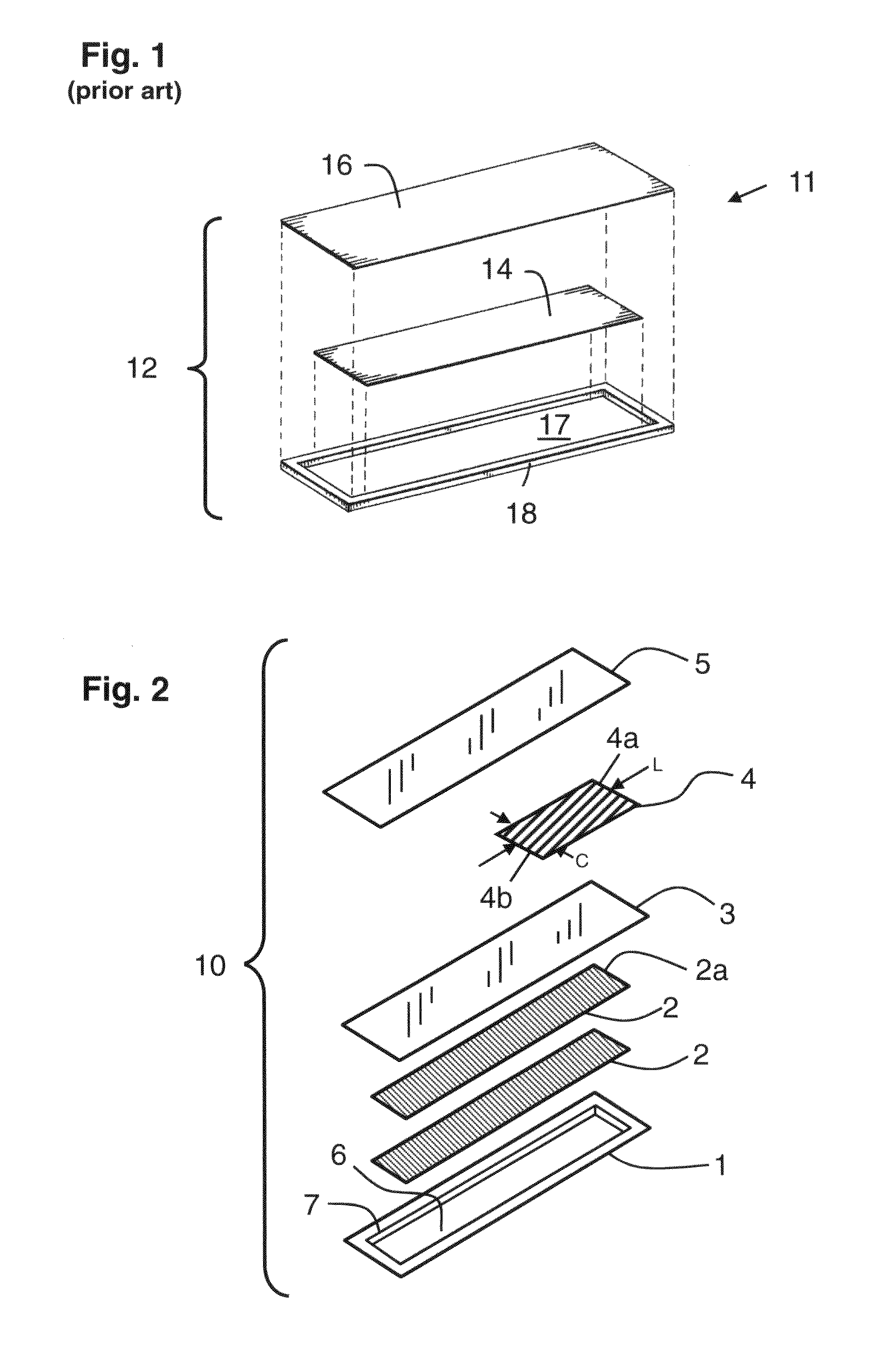
[0018]In one aspect, the present invention provides a non-deactivatable magnetomechanical marker and an electronic article surveillance system using such a marker. The marker can be produced inexpensively and with high yield. It is exceedingly robust and highly reliable in operation. It exhibits magnetomechanical resonance at a marker resonant frequency in response to the incidence thereon of an electromagnetic interrogating field. The marker comprises: (i) a magnetomechanical element comprising at least one, and preferably two or more, elongated resonator strips composed of unannealed magnetostrictive amorphous metal alloy; (ii) a housing having a cavity sized and shaped to accommodate the magnetomechanical element, the one or more resonator strips being disposed in the cavity and able to mechanically vibrate freely therewithin; and (iii) a bias element, such as a strip of semi-hard or hard magnetic material, that is adapted to be magnetized to magnetically bias the magnetomechanical element while being strongly resistant to deactivation. The biasing field arms the magnetomechanical element to resonate at the marker resonant frequency in the presence of an electromagnetic interrogating field. In some embodiments, a plurality of resonator strips are used to comprise the magnetomechanical element and are disposed in the cavity in stacked registration. In some embodiments, these resonator strips are of substantially the same length so that they resonate at substantially the same frequency. Other embodiments employ plural strips having a plurality of preselected resonant frequencies to provide a coded marker, such as a marker of the type disclosed by the '490 patent. Marker implementations in which deactivation is not required are preferably constructed using bias elements formed from material having a coercivity of 1000 Oe or more. Preferred materials for these implementations include magnetic materials comprising a magnetic powder, such as a barium ferrite or a rare earth-base metal alloy, embedded in a rigid or flexible matrix, such as rubber or other polymer. Such materials are generally known in the art as bonded magnets.
[0021]As a result of the foregoing adaptive control, based on measurement of the resonant frequencies of finished markers during the production, the sequence exhibits a tight distribution of frequencies, improving the production yield of markers and the reliability of EAS system operation. Moreover, the control permits industrially viable construction of markers wherein the magnetostrictive element comprises plural strips of unannealed, magnetostrictive amorphous metal alloy. Such markers are smaller and are more easily and reliably produced than previous markers, which have required either a larger footprint or use of annealed magnetic materials.

Problems solved by technology

In practice, harmonic EAS systems encounter a number of problems.
A principal difficulty stems from the superposition of the harmonic signal and the far more intense signal at the fundamental interrogation frequency.
Harmonic systems are also known to be vulnerable to false alarms arising from massive ferrous objects (such as shopping carts) also present in a typical retail environment.
However, known magnetomechanically resonant markers comprising magnetostrictive material and systems employing such markers, including those of the types disclosed by the '489 and '490 patents, have a number of characteristics that render them undesirable for certain applications.
Attempts to reduce the size of the marker encounter certain obstacles.
In general, reducing the volume of the resonating magnetic element proportionally reduces the detectable signal from the marker and the size of the interrogation zone within which the marker is responsive, hindering reliable detection.
The '563 patent further discloses that prior art ribbon optimized for a multiple resonator tag is unsuitable for a single resonator marker and vice versa.
These non-deactivatable, ferrite containing tags are expensive.

Method used


Image

  • Electronic article surveillance marker
  • Electronic article surveillance marker
  • Electronic article surveillance marker

Examples


example 1

Short Duration Marker Production And Testing

[0085]A series of magnetomechanical EAS labels having a natural resonant frequency for magnetomechanical oscillation are produced using a continuous-feed, web-based press. Each label comprises a housing having a cavity, two resonator strips disposed in the cavity to form a magnetomechanical element, and a bias magnet adjacent the resonator strips. The production is accomplished using a press adapted to carry out, in sequence, the following steps: (i) embossing cavities in a high-impact polystyrene-polyethylene laminate webstock material; (ii) cutting magnetostrictive amorphous metal ribbon stock using a resonator strip cutter system to form resonator strips having a preselected resonator strip length; (iii) extracting two of the resonator strips from the cutter system; (iv) disposing the extracted strips in each cavity in stacked registration; (v) covering and sealing each cavity with a lidstock material that confines the resonator strips ...

example 2

Extended Duration Marker Production And Testing

[0089]The efficacy of the adaptive feedback label production system used for the experiments of Example 1 is tested during extended duration production. The system is operated in a normal factory production schedule to produce labels using the same nominal resonator and bias materials employed in Example 1. However, multiple supply lots are used over several days' worth of production. The press is operated for several days each without and with use of the adaptive resonator strip length control. Results are set forth in Table II below.

TABLE IIProduction Statistics For EAS Label FabricationfeedbackaveragestandardRunmodefrequencydeviationNo.(on / off)(Hz)(Hz)A1off58096634B1off58087733A2on58067273B2on58055336

[0090]Although Runs A1 and B1 both achieve an average resonant frequency close to the desired 58050 Hz value, the standard deviation over the production run of over 1,000,000 markers is substantially larger than the standard deviations a...

example 3

Extended Duration Marker Production And Testing

[0091]An implementation of the present marker fabrication press and process employing an extractor using a permanent magnet disposed below the traversing webstock is used for high-rate production of markers. The markers are formed using METGLAS® 2826MB3 resonator strips and ARNOKROME™ 5 semi-hard magnet alloy strips as bias elements. An in-line frequency measurement and control system is used to adaptively adjust the resonator strip cut length during fabrication of a sequence of markers. The measurement system includes a single coil used for both transmit and receive functions, the coil being electrically switched under computer control between transmitter circuitry during pulse excitation of the marker under test and receiver circuitry to sense the subsequent resonant ringdown of the marker. Alternate markers in the production sequence are thus tested.

[0092]The efficacy of the adaptive feedback label production system in maintaining a ...


PUM

PropertyMeasurementUnit
Fractionaaaaaaaaaa
Auxiliary magnetic fieldaaaaaaaaaa
Coercivityaaaaaaaaaa

Abstract

A fabrication process produces markers for a magnetomechanical electronic article surveillance system. The marker includes a magnetomechanical element comprising one or more resonator strips of magnetostrictive amorphous metal alloy; a housing having a cavity sized and shaped to accommodate the resonator strips for free mechanical vibration therewithin; and a non-deactivatable bias magnet adapted to magnetically bias the magnetomechanical element. The process employs adaptive control of the cut length of the resonator strips, correction of the length being based on deviation of the actual marker resonant frequency from a preselected, target marker frequency. Use of adaptive, feedback control advantageously results in a much tighter distribution of actual resonant frequencies. Also provided is a web-fed press for continuously producing such markers with adaptive control of the resonator strip length.

Description

RELATED U.S. APPLICATION DATA[0001]This application is a continuation-in-part of co-pending U.S. application Ser. No. 12 / 008,739, filed Jan. 14, 2008, which, in turn, is a continuation-in-part of U.S. application Ser. No. 12 / 008,734 filed Jan. 14, 2008, which, in turn, is a continuation-in-part of U.S. application Ser. No. 11 / 981,999 filed Oct. 31, 2007, which, in turn, is a continuation-in-part of U.S. application Ser. No. 11 / 705,946, filed Feb. 14, 2007, and further claims the benefit of U.S. Provisional Application Ser. No. 60 / 773,763, filed Feb. 15, 2006, entitled “Electronic Article Surveillance Marker,” which applications are incorporated herein in their entirety by reference thereto.BACKGROUND OF THE INVENTION[0002]1. Field Of The Invention[0003]The present invention relates to an electronic article surveillance system and a non-deactivatable marker for use therein; and more particularly, to a process for fabricating a magnetomechanically resonant, non-deactivtable marker wit...

Claims


Application Information

Patent Timeline
IPC IPC(8): G08B13/14H01F7/06B65B63/00
CPCG08B13/2408G08B13/2437Y10T29/4902G08B13/2442H01F1/153G08B13/244
Inventor PETER, JOHANNES MAXMILLIANHIBSHMAN, MARK THOMASSERGEANT, JOHNATHAN DALE
Owner PHENIX LABEL
Learn More