
Fiber-Reinforced Thermoplastic Resin Composition, Method for Producing the Same, and Carbon Fiber for Thermoplastic Resin

a thermoplastic resin and fiber-reinforced technology, which is applied in the direction of transportation and packaging, organic dyes, coatings, etc., can solve the problems of increasing the viscosity of the thermoplastic resin composition comprising reinforcing fibers, affecting the appearance affecting the strength of the molded product, etc., to achieve superior mechanical properties, good interface adhesion, and impact resistance.

Inactive Publication Date: 2009-06-04
TORAY IND INC
View PDF1 Cites 32 Cited by
  • Summary
  • Abstract
  • Description
  • Claims
  • Application Information

AI Technical Summary

Benefits of technology

[0026]According to the present invention, good interface adhesion between reinforcing fibers and thermoplastic resin can be realized. Thus, a fiber-reinforced thermoplastic resin composition that is significantly superior in mechanical properties such as strength properties and impact-resistant properties can be obtained. A molded product comprising such fiber-reinforced thermoplastic resin composition is preferably used for electric or electronic apparatus, office automation apparatus, parts of electric household appliances or automobiles, internal members, housings, and the like.

Problems solved by technology

However, increased reinforcing fiber content results in an increase in the viscosity of a thermoplastic resin composition comprising reinforcing fibers.
As a result, in addition to loss of molding processability, the appearance of a molded product deteriorates.
Further, strength reduction often occurs due to the generation of areas unfilled with thermoplastic resin.
In some cases, sufficient interface adhesion cannot be achieved.
However, if the amount of oxidation treatment for carbon fiber is increased, the graphite structure of a carbon fiber surface is destroyed, resulting in strength reduction in the carbon fiber itself.
In such case, such strength reduction may negatively influence mechanical properties of a molded product.
However, in some cases, due to the limitation in the surface area subjected to oxidation treatment, functional groups in a sufficient amount for a reaction with a sizing agent are not imparted to the surfaces of carbon fibers subjected to a usual oxidation treatment.
Further, some types of sizing agents have poor reactivity with functional groups on carbon fiber surfaces.
Furthermore, when a compound having a highly hydrophilic bond such as a urethane bond or an amide bond is used as a sizing agent, a molded product tends to absorb water.
Accordingly, mechanical properties might deteriorate.
Thus, in some cases, the interface becomes weak or degradation occurs at a temperature at which the processing of a fiber-reinforced thermoplastic resin composition takes place, resulting in an insufficient chemical reaction of a functional group on a carbon fiber surface and a functional group of thermoplastic resin.
Further, mechanical properties of a molded product may deteriorate due to the generation of voids of cracked gas.
In addition, in some cases, such low-molecular-weight compound disperses in thermoplastic resin before chemically reacting with a functional group on a carbon fiber surface, so that sufficient interface adhesion cannot be obtained.
Therefore, a molded product superior in strength properties and impact-resistant properties cannot be obtained by conventional methods, which has been problematic.

Method used


Image

  • Fiber-Reinforced Thermoplastic Resin Composition, Method for Producing the Same, and Carbon Fiber for Thermoplastic Resin
  • Fiber-Reinforced Thermoplastic Resin Composition, Method for Producing the Same, and Carbon Fiber for Thermoplastic Resin
  • Fiber-Reinforced Thermoplastic Resin Composition, Method for Producing the Same, and Carbon Fiber for Thermoplastic Resin

Examples


example 1

I. Step of Applying a Sizing Agent

[0253]A 5%-by-weight solution of A-1 (acrylic polymer) was prepared as a sizing agent and then applied to B-1 (carbon fiber) by a dipping method, followed by drying at 140° C. for 5 minutes. The amount of adhering A-1 (acrylic polymer) was 1.5 parts by weight with respect to 100 parts by weight of B-1 (carbon fiber).

II. Step of Cutting Fiber

[0254]B-1 (carbon fiber) to which the sizing agent had adhered in the above step 1 was cut to ¼ inch in size with a cartridge cutter.

III. Extrusion Step

[0255]A TEX-30α biaxial extruder (screw diameter: 30 mm, L / D=32) (the Japan Steel Works, LTD.) was used. C-1 (anhydrous maleic acid-modified polypropylene resin pellet) was supplied from the main hopper and B-1 (carbon fiber) that had been cut in the previous step was supplied from the side hopper downstream thereof. Then, sufficient kneading was carried out at a barrel temperature of 220° C. and at 150 rpm, followed by deaeration via a vacuum vent located further...

example 2

[0257]Example 2 was carried out in the same manner as Example 1, except that C-2 (mixture of native polypropylene resin and acid-modified polypropylene resin) was used instead of C-1 (anhydrous maleic acid-modified polypropylene resin pellet) in step III in Example 1. Table 1 shows evaluation results for the obtained molded product. The content of B-1 (carbon fiber) in the molded product was 20% by weight.

example 3

[0258]Example 3 was carried out in the same manner as Example 1 except that A-2 (acrylic polymer) was used instead of A-1 (acrylic polymer) in step 1 in Example 1. Table 1 shows evaluation results for the obtained molded product. The content of B-1 (carbon fiber) in the molded product was 20% by weight.


PUM

PropertyMeasurementUnit
mol %aaaaaaaaaa
number-average fiber lengthaaaaaaaaaa
acid valueaaaaaaaaaa

Abstract

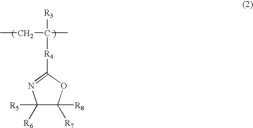
According to the present invention, a fiber-reinforced thermoplastic resin composition that is superior in adhesivity between reinforcing fiber and thermoplastic resin is provided. It is possible to sufficiently improve mechanical properties of a molded product with such composition. Such fiber-reinforced thermoplastic resin composition comprises a (meth)acrylic polymer (A1) having an aminoalkylene group in a side chain or a polymer having an oxazoline group (A2) (0.1% to 10% by weight), reinforcing fibers (B) (1% to 70% by weight), and a thermoplastic resin (C) (20% to 98.9% by weight).

Description

TECHNICAL FIELD[0001]The present invention relates to a fiber-reinforced thermoplastic resin composition, a method for producing the same, and carbon fibers for thermoplastic resin. A molded product comprising the fiber-reinforced thermoplastic resin composition of the present invention has good interface adhesion between reinforcing fibers and thermoplastic resin, and thus it is superior in strength properties and impact-resistant properties. Therefore, it is preferably used for electric or electronic apparatus, office automation apparatus, parts of electric household appliances or automobiles, internal members, housings, and the like.BACKGROUND ART[0002]Compositions comprising reinforcing fibers and thermoplastic resin have been widely used for automobile and electric or electronic apparatus applications because they are lightweight and have excellent mechanical properties.[0003]Various forms of reinforcing fibers used for the above fiber-reinforced thermoplastic resin composition...

Claims


Application Information

Patent Timeline
Patent Type & Authority Applications(United States)
IPC IPC(8): C08K3/34B05D3/02C08L33/08C08L37/00B32B37/06
CPCC08J5/042C08J5/044C08J2323/02C08J2323/26C08K7/02Y10T428/2918C08L33/14C08L23/10C08L2666/04C08L2666/02C08J5/0405C08J5/04C08L33/06
Inventor NAKAYAMA, YOSHIFUMIHONMA, MASATO
Owner TORAY IND INC
Learn More