
Manufacturing method of soi substrate and manufacturing method of semiconductor device

Inactive Publication Date: 2009-01-01
SEMICON ENERGY LAB CO LTD
View PDF46 Cites 26 Cited by
  • Summary
  • Abstract
  • Description
  • Claims
  • Application Information

AI Technical Summary

Benefits of technology

[0010]An ion doping apparatus for irradiation with ions by the ion doping method is an apparatus which was developed for manufacturing thin film transistors over a glass substrate with each side over one meter. Therefore, the ion doping method has an advantage in that the tact time for forming a damaged region can be reduced, over the ion implantation method in which mass separation is performed. However, in the ion doping method, a metal element contained in a material of an electrode or the like of an ion doping apparatus may be injected into a silicon wafer together with the hydrogen ions because mass separation is not performed. An SOI substrate contaminated by a metal causes decrease in electrical characteristics and reduction in reliability of a transistor, such as change of threshold voltage of a transistor and increase of leakage current.
[0031]Since the heat treatment for gettering a metal element with the gettering site layer or the gettering site region can be performed below the distortion temperature of a glass substrate, a glass substrate can be used as the base substrate to which the semiconductor layer is attached. Accordingly, a high-performance, highly reliable semiconductor device can be manufactured over a glass substrate.

Problems solved by technology

However, in the ion doping method, a metal element contained in a material of an electrode or the like of an ion doping apparatus may be injected into a silicon wafer together with the hydrogen ions because mass separation is not performed.
An SOI substrate contaminated by a metal causes decrease in electrical characteristics and reduction in reliability of a transistor, such as change of threshold voltage of a transistor and increase of leakage current.

Method used


Image

  • Manufacturing method of soi substrate and manufacturing method of semiconductor device
  • Manufacturing method of soi substrate and manufacturing method of semiconductor device
  • Manufacturing method of soi substrate and manufacturing method of semiconductor device

Examples


embodiment mode 1

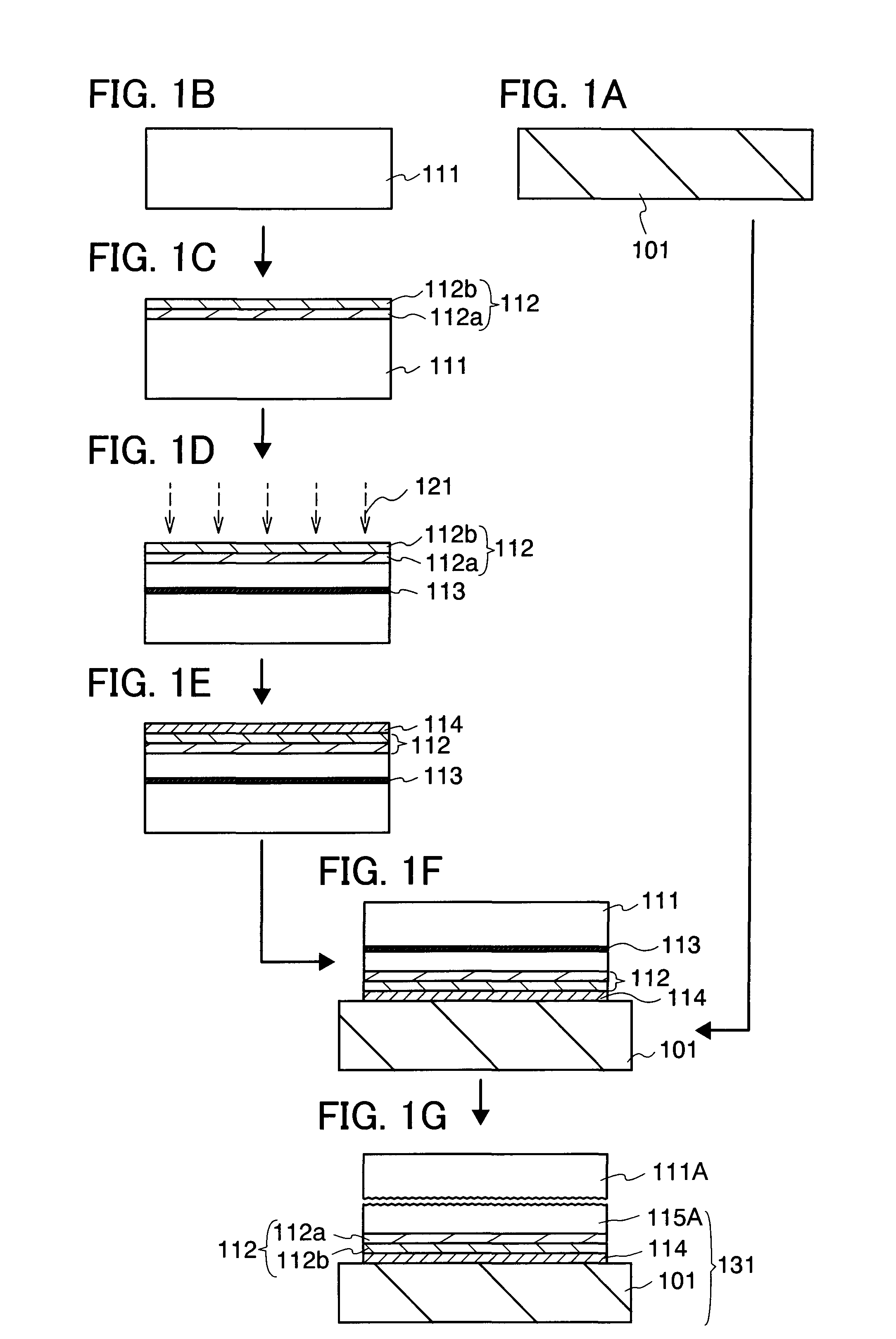
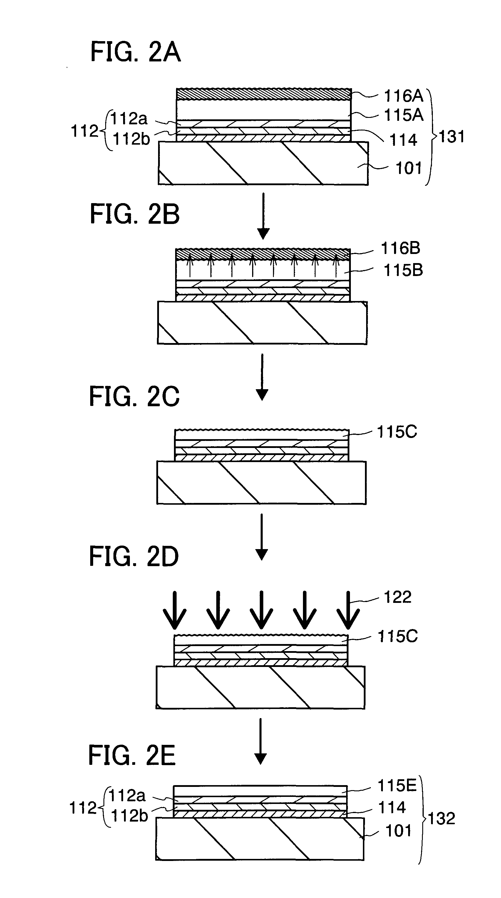
[0051]A method for manufacturing an SOI substrate will be described using FIGS. 1A to 1G, and 2A to 2E in this embodiment mode. FIGS. 1A to 1G, and 2A to 2E are cross-sectional views showing one example of a manufacturing method of an SOI substrate.

[0052]As shown in FIG. 1A, a base substrate 101 is prepared. The base substrate 101 is a support substrate for supporting a semiconductor layer separated from a semiconductor substrate. As the base substrate 101, a light-transmitting glass substrate used for electronics industry such as a liquid crystal display device can be used. In terms of heat resistance, cost, and the like, it is preferable to use a glass substrate having a coefficient of thermal expansion which is higher than or equal to 25×10−7 / ° C. and lower than or equal to 50×10−7 / ° C. (more preferably, higher than or equal to 30×10−7 / ° C. and lower than or equal to 40×10−7 / ° C.) and a distortion temperature which is higher than or equal to 580° C. and lower than or equal to 700...

embodiment mode 2

[0114]A method for manufacturing an SOI substrate, which is different from the method described in Embodiment Mode 1 will be described in this embodiment mode. FIGS. 3A to 3E are cross-sectional views showing one example of a manufacturing method of an SOI substrate.

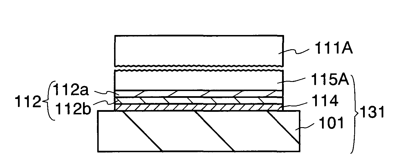
[0115]The SOI substrate 131 is formed by performing the steps described using FIGS. 1A to 1G. FIG. 3A is a cross-sectional view of the SOI substrate 131. The SOI substrate 131 is a substrate in which the bonding layer 114, the insulating layer 112, and the semiconductor layer 115A are stacked over the base substrate 101. In this embodiment mode, steps shown in FIGS. 3B to 3E are performed, so that a metal element of the semiconductor layer 115A is removed and the crystallinity of the semiconductor layer 115A is improved.

[0116]Since crystal defects are formed by the ion irradiation step or the like in the semiconductor layer 115A of the SOI substrate 131, heat treatment for improving the crystallinity of the semiconductor...

embodiment mode 3

[0127]A method for manufacturing an SOI substrate, which is different from the method described in Embodiment Mode 1 will be described in this embodiment mode. FIGS. 4A to 4E are cross-sectional views showing one example of the manufacturing method of an SOI substrate in this embodiment mode.

[0128]First, the SOI substrate 131 is formed by performing the steps described using FIGS. 1A to 1G. The SOI substrate 131 is a substrate in which the bonding layer 114, the insulating layer 112, and the semiconductor layer 115A are stacked over the base substrate 101. Next, gettering of removing a metal element of the semiconductor layer 115A of the SOI substrate 131 is performed.

[0129]First, a gettering site region 117A is formed in an upper portion of the semiconductor layer 115A. FIG. 4A is a cross-sectional view for describing the step of forming the gettering site region 117A.

[0130]The gettering site region 117A is formed by irradiating the semiconductor layer 115A with an ion beam 123 con...


PUM


Abstract

An effect of metal contamination caused in manufacturing an SOI substrate can is suppressed. A damaged region is formed by irradiating a semiconductor substrate with hydrogen ions, and then, a base substrate and the semiconductor substrate are bonded to each other. Heat treatment is performed thereon to cleave the semiconductor substrate, so that an SOI substrate is manufactured. A gettering site layer is formed of a semiconductor containing a Group 18 element such as Ar, over a semiconductor layer of the SOI substrate. Heat treatment is performed thereon to perform gettering of a metal element in the semiconductor layer with the gettering site layer. By removing the gettering site layer by etching, thinning of the semiconductor layer can be performed.

Description

BACKGROUND OF THE INVENTION[0001]1. Field of the Invention[0002]The present invention relates to a manufacturing method of an SOI (silicon on insulator) substrate having a semiconductor layer formed of silicon or the like and a method for manufacturing a semiconductor device by using the SOI substrate.[0003]Note that the ‘semiconductor device’ in this specification refers to a device in general that can operate by utilizing semiconductor characteristics, and an electro-optical device, an integrated circuit, and an electronic device are all included in the category of the semiconductor device.[0004]2. Description of the Related Art[0005]Integrated circuits using an SOI substrate in which a thin single-crystal silicon layer is formed over an insulating layer have been developed. By utilizing characteristics of the thin single-crystal silicon layer, transistors in the integrated circuit can be formed so as to be completely isolated electrically for each element, and the transistors can...

Claims


Application Information

Patent Timeline
IPC IPC(8): H01L21/46
CPCH01L21/76254H01L29/66772H01L27/1266H01L27/1214H01L21/20H01L27/12
Inventor SHIMOMURA, AKIHISAMIYAIRI, HIDEKAZUSATO, YURIKA
Owner SEMICON ENERGY LAB CO LTD
Learn More