
Filter structure for iterative signal processing

a filter structure and iterative signal technology, applied in the field of wireless communication, can solve the problems of corrupt transmissions, limited performance quality in terms of how many users (capacity) can share resources simultaneously, interference between all active users,

Inactive Publication Date: 2008-12-25
COHDA WIRELESS
View PDF27 Cites 95 Cited by
  • Summary
  • Abstract
  • Description
  • Claims
  • Application Information

AI Technical Summary

Benefits of technology

[0105]In a particular embodiment, the above steps a) to e) for estimating offsets may be used effectively as a means of channel estimation. For example, in the above described form of the invention which provides communication by estimating time varying channel impairments, the step c) of updating the set of channel impairment estimates with the determined set of symbol estimates and received packet may comprise the above steps a) to e) for estimating offsets.
[0157]Furthermore, the present invention enables all decoder outcomes to be employed (decoder outcomes are stored across all iterations and able to be combined) in the receiver filter structure providing improved estimate determination. The number of users that may be supported is greatly increased. Particularly advantageous, for example, in OFDM systems the present invention does not require prohibitively large matrices to be inverted in forming estimates. Receiver performance is superior to that of the related art due to the quality of the feedback symbol provided by including decoding in the iteration loop. Embodiments of the present invention are based on interference cancellation where previous estimates of the multi user received signals are subtracted from the received signal to cancel the interference they cause. Accordingly, these embodiments do not suffer the disadvantages and complexities of using tree search methodologies for multiuser signals which would necessitate exploring many paths through a given tree. The present invention advantageously enables decoding of each user's signal according to their Forward Error Correction encoding. This use of strong error control code structure provides for significantly improved symbol estimates, resulting in superior interference estimates. This in turn allows support for significantly higher numbers of users. Embodiments of the present invention do not require synchronised users to enable improved multi user reception. Embodiments of the present invention advantageously use decoder outcomes as training symbols rather than only using demodulator outcomes. Advantageously, receiver coefficients for beamforming may be determined without transmitter interaction. Also the use of decoder outcomes to improve channel estimates allows accurate estimation of the required beamforming coefficients. In accordance with embodiments of the present invention, smoothing of channel estimate taps is performed in the frequency domain as well as the time domain. Further to this, embodiments of the present invention allow decoding of symbols more than once as a channel estimate corresponding to its interval is improved resulting in increased receiver sensitivity.

Problems solved by technology

In most cases, sharing resources in a multiple access system means that if more than one user is active, then all active users interfere with each other.
Traditionally, such interference has been considered to be part of the inevitable noise that corrupts transmissions.
Such interference increases with the number of active users and thus, the performance quality in terms of how many users (capacity) that can share the resources simultaneously becomes limited.
Commonly the users may be required to share the radio resource by, for example, transmitting on different frequencies or at different times. Such techniques may be wasteful in terms of the expensive radio resource.
This decoding strategy may increase capacity significantly, getting very close to theoretical capacity limits at a complexity level within reach of practical implementation.
However, an optimal multiuser detector is prohibitively complex for practical implementation, as the inherent complexity grows exponentially with the number of active users.
Channel resources such as available bandwidth are typically strictly limited in a wireless environment.
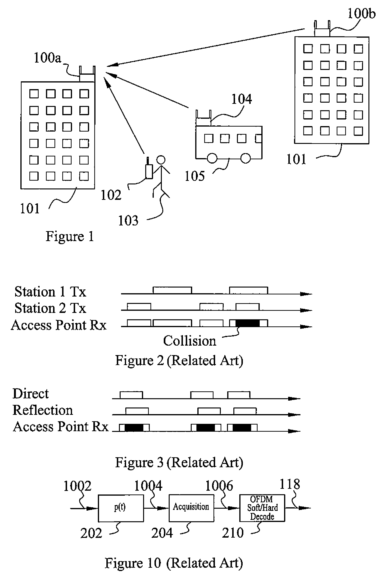
Allowing multiple users to share common resources creates a risk for disturbances and interference caused by colliding access attempts.
Physical layer receivers may fail to recover such collided packets.
As the traffic load on the network increases, this problem becomes a significant limiting factor in terms of network capacity and quality of service.
A different problem, leading to similar effects, is caused by the multipath nature of communication channels associated with, for example, a WLAN.
This, in turn, creates self-interference similar in nature to multiple access interference discussed above.
In this case, the problem becomes a limiting factor for the required power to achieve acceptable performance, which translates into limitations on the coverage of the WLAN.
However, there are drawbacks with this technique in as much as signal distortions may be amplified or accentuated by the processing involved with the synchronization process producing uncertainties in the determination of packet timing.
Moreover, receiver processes are unable to determine the variation of a radio channel over the time of a packet length and the associated effect on the waveform of the transmitted signal.
This may lead to lower than optimum data rates due to poorly tracked packets that are otherwise intact being discarded.
In OFDM packet based communication systems channel impairments may occur, which contribute to changing both the channel over which an OFDM signal travels and also the received signal itself.
Other methods use data estimates to aid for example with channel estimation and these are implemented in the frequency domain and may result in power loss by discarding a cyclic prefix for each received symbol.
Generally, there is no use made of all available received information to address channel impairments in such packet based communication systems.
These approaches do not address the variation of signal statistics across the number of antennae resulting in degraded synchronization accuracy and increased packet loss.
However, EP 1381544 relates to a system which makes use of a streaming signal and not readily adapted for the random arrival of packets.
In this disclosure the raw channel estimates are stored and a smoothing step is executed every time the data base is accessed, which entails a relative degree of complexity.
There are many other types of FEC systems that do not employ ML decoding (e.g. Soft Output Decoders such as A-Posterior Probability techniques) and, moreover, for which Chuang is not adapted to operate within.
Errors in this estimate may result in signal power loss or failures in the synchronisation of high layer structures such as error control coding and FFT windows.
Errors in this estimate may result in demodulator failure and subsequent packet decode failure.

Method used


Image

  • Filter structure for iterative signal processing
  • Filter structure for iterative signal processing
  • Filter structure for iterative signal processing

Examples


first embodiment

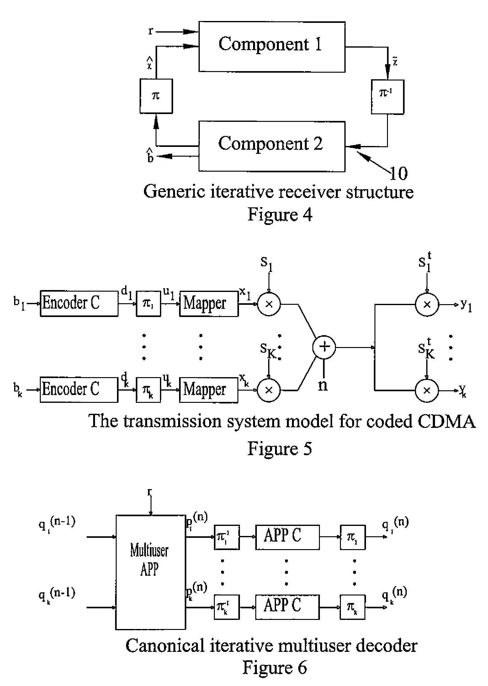
[0205]An innovation in the filter design of a first embodiment disclosed herein is to exploit the fact that information provided by the decoders is initially only marginally correlated over iterations, i.e. in the first few iterations, each iteration provides new information. As the structure converges, the output of the decoders also converges and eventually becomes completely correlated.

[0206]The disclosed filter design is based on a technique to use all available information from all previous iterations. This implies that the filter grows linearly in size by a factor equal to the number of users. This is clearly impractical. Thus, the disclosed filter design makes it possible to use all the available information through recursive feedback of the filter output over iterations, without requiring a growing filter. The size of the filter remains the same. In order to achieve this, the filters in the structure may be designed according to the recursive expressions derived herein.

[0207...

second embodiment

[0268]With reference to FIGS. 10 to 18 a second embodiment is described where there are a number of specific solutions offered which fall out from the general solution of (or realization that) adapting related art single pass OFDM receivers to iteratively receive signals at the sampling level allows the receiver to differentiate a desired packet from an observation of an interference (collision) signal at the receiver input. These solutions are as follows:[0269]An overall system solution—Iterative Receiver Structure itself.[0270]Additional solution aspect—Samples Estimates list.[0271]Additional solution aspect—Information Bit Estimates list.[0272]Additional solution aspect—Multiplexing of Time / Frequency Domain Channel Application Sample Estimates.

[0273]In one aspect, the second embodiment provides a system and method of receiving OFDM packets comprising the following:

[0274]a) sample a receiver input signal consisting of signals from one or more antenna;

[0275]b) add the input signal ...

third embodiment

[0386]With reference to FIGS. 19 to 23 a third embodiment is described which stems from the realization that reducing the distortions in one or more of the raw signals arriving at a receiver used to provide a decision statistic leads to an overall improvement in the decision statistic itself. Furthermore, appropriate selection of the means of reducing these distortions leads to a more reliable determination of packet arrival time.

[0387]In one aspect the third embodiment provides a method and apparatus for communicating in a multiple access communication network by synchronizing packets arriving at a receiver comprising:

[0388]receiving a packet input signal;

[0389]determining a correlation signal corresponding to the packet input signal;

[0390]processing the input and correlation signals such that at least one of the input signal and the correlation signal are filtered;

[0391]determining a decision statistic by combining a power component of the processed correlation signal with a power...


PUM


Abstract

The present invention relates to improved multiple access communications. In one form, the invention relates to an improved signal processing method and apparatus for an iterative method of determining the reception of a signal in a multi user packet based wireless OFDM (Orthogonal Frequency Division Multiplexing) communication system. In other forms the present invention provides recursive filtering for joint iterative decoding in a variety of systems and functions such as linear multiple access channel decoders, iterative equalisation, iterative joint channel estimation and detection / decoding, iterative space-time processing, iterative multi user interference cancellation and iterative demodulation. In one particular form the present invention provides an iterative decoding circuit for a wireless multiuser communications receiver comprising a first signal processing means for receiving at least one received signal, said first signal processing means comprising at least two linear iterative filters such that the first linear iterative filter provides an estimate of a selected received signal to an estimated signal output and a second linear iterative filter provides estimates of at least one other received signal, delayed by one iteration cycle, to an input of said first linear iterative filter, a second signal processing means for receiving the estimated signal output of the first linear iterative filter and providing a further received signal estimate to the input of the first signal processing means in a succeeding iteration cycle of the decoding circuit.

Description

RELATED APPLICATIONS[0001]This application is a division of U.S. patent application Ser. No. 10 / 897,886 filed 23 Jul. 2004, which claims benefit of and is a continuation-in-part of co-pending international application No. PCT / AU03 / 00502 entitled “Filter Structure for Iterative Signal Processing”, filed 29 Apr. 2003, now WO 03 / 094037, which takes priority from Australian Provisional Patent Application No. PS2053, filed 2 May, 2002, also entitled “Filter Structure for Iterative Signal Processing” and further claims benefit from Australian Provisional Patent Application No. 2003903826, filed 24 Jul. 2003, entitled “An OFDM Receiver Structure”. The specifications of and, International application (PCT) are incorporated herein by reference in their entirety and for all purposes.FIELD OF INVENTION[0002]The present invention relates to the field of wireless communications. In particular, the present invention relates to improved multiple access communications. In one form, the invention re...

Claims


Application Information

Patent Timeline
IPC IPC(8): H04L27/28H04J3/06H04B1/10H04L27/06H04L25/02H04L25/03H04L27/26
CPCH04L25/0204H04L25/03171H04L27/2657H04L27/2662H04L27/2675H04L25/0202H04L27/26
Inventor ALEXANDER, PAUL DEANGRANT, ALEXANDER JAMESRASMUSSEN, LARS KILDEHOJJAKAS, STEPHEN PETER
Owner COHDA WIRELESS
Learn More