
Heat-resistant light-shading film and production method thereof, and diaphragm or light intensity adjusting device using the same

a technology of heat-resistant lightshade and film, which is applied in the direction of instruments, applications, other domestic objects, etc., can solve the problems of metal plates grazing, large noise, and blade grazing, and achieves low deterioration of sliding and surface gloss characteristics, high electroconductivity, and high durability

Inactive Publication Date: 2008-10-16
SUMITOMO METAL MINING CO LTD
View PDF5 Cites 7 Cited by
  • Summary
  • Abstract
  • Description
  • Claims
  • Application Information

AI Technical Summary

Benefits of technology

[0022]Thus, an object of the present invention is, in a light-shading film with a substrate film having a finely concavity and convexity structure on the surface of a substrate film, used as light intensity adjusting blades for liquid-crystal projectors, which are exposed to high temperature, or shutter blades and fixed diaphragm for digital cameras, which are exposed to high temperature in the processing step, to provide a heat-resistant light-shading film having high electroconductivity showing little deterioration of sliding and surface gloss characteristics, high durability making the film resistant to deformation and discoloration, and with no peel-off of the film and no drop-off of the shot material.
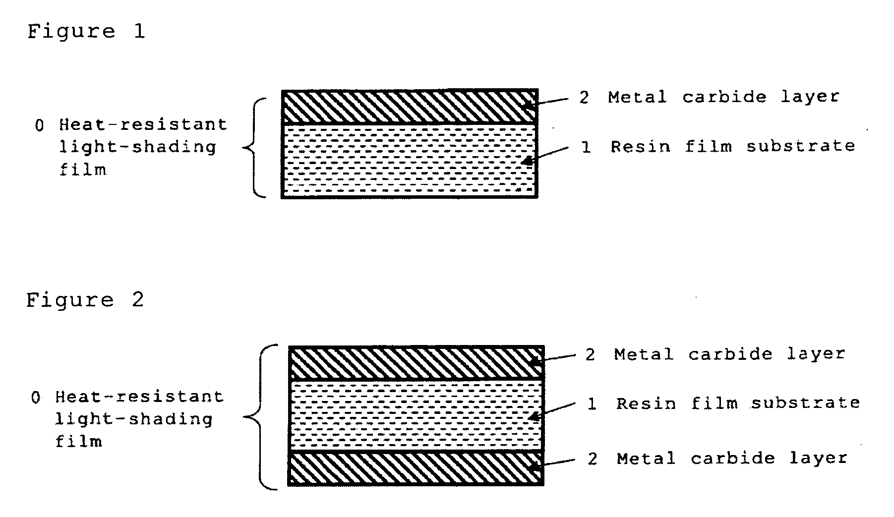
[0023]The inventors of the present invention have found, after having studied to solve the above-described problems involved in the conventional techniques, that a heat-resistant light-shading film showing little deformation, keeping characteristics (high light-shading capacity, low surface gloss, high sliding characteristics, color and low reflectance) in high temperature environments of 155° C. or higher, and around 200° C. depending on type of the substrate, and useful for diaphragm members for digital cameras, digital video cameras, liquid-crystal projectors and so forth, can be obtained by using a heat-resistant resin film (A) having heat resistance of 155° C. or higher as a substrate as a resin film having a fine concavity and convexity on the surface, and forming a light-shading layer (B), which is a crystalline metal carbide layer (sometimes described as MeC in specification) having a specified thickness, by sputtering method while surface temperature of the resin film substrate (A) is maintained at 155° C., and accomplished the present invention.
[0044]Since, in the heat-resistant light-shading film of the present invention, a metal carbide layer having a specific thickness is formed on a heat-resistant resin film substrate having a surface roughness of 0.2 to 2.2 μm in arithmetic average height Ra, a heat-resistant light-shading film having a low surface gloss, a low reflectance and an electroconductivity can be realized. In addition, since said metal carbide film layer is formed by sputtering method, it secures denser surface structure than a light-shading film produced by a conventional coating procedure, and has improved surface wear resistance and friction resistance. In addition, since, in the heat-resistant light-shading film of the present invention, on a resin film substrate having a heat resistance of 155° C. or higher, a crystalline metal carbide layer is formed as a light-shading layer, said metal carbide material is less susceptible to oxidation and light-shading capacity hardly varies in a high temperature environment at 155 to 300° C. or a high humidity environment, therefore, it has a more superior heat resistance compared with a heat-resistant light-shading film using a conventional oxidizable metal layer as a light-shading layer. In addition, since the heat-resistant light-shading film of the present invention has a symmetrical layer structure having the heat-resistant resin film at the center sandwiched with the metal carbide layers, deformation in the sputtering time due to film stress does not occur, providing high productivity.
[0046]The light intensity adjusting device of the present invention, which uses light-shading blades produced by processing said heat-resistant light-shading film, is more reduced in weight due to the light-shading blades made of resin film substrate compared with a light intensity adjusting device using light-shading blades produced by processing a conventional heat-resistant light-shading film made of metal foil plate coated with heat-resistant coating material. Therefore, when the heat-resistant light-shading film is used for diaphragm blade and the like, it improves sliding characteristics, enables down-sizing of driving motor, and leads to cost reduction.

Problems solved by technology

When a light-shading film supported by a metallic substrate is used as a shutter blade or diaphragm blade in a camera, the metallic plates will graze with each other when the blades are opened and closed to generate large noise.
In addition, in a liquid-crystal projector, the blade is required to move at a high speed to reduce brightness changes when images are changed, with the result that the blades will graze with each other to repeatedly generate noise.
In addition, to operate the blades at a lower speed to reduce noise caused a problem to produce unstable images, because light intensity adjustment may not sufficiently follow changed images.
However, when a lamp light source becomes a high output, polyethylene terephthalate (PET) has a low thermal deformation temperature and low mechanical strength such as tensile modulus, with the result that light-shading blades of polyethylene terephthalate may be deformed by vibrations and shocks and the like generating in the running or braking period as output of light sources.
In these severe environments, the conventional light-shading films described above showed unfavorable phenomena in durability such as, e.g., deformation or discoloration, and caused problems in practical use.
Light-shading films, when used at high temperature environment of 155° C. or higher, will be greatly deformed by heat, even when they have a fine concavity and convexity structure on the surface, with the result that they can no longer work at a high speed when they come into contact with each other, and have deteriorated sliding characteristics and surface gloss because they are grazing with each other more frequently irregularly.
As a result, digital cameras, digital video cameras or liquid-crystal projectors, may no longer exhibit their intended functions.
These troubles can have adverse effects on the surrounding parts, and generate a problem that the intended functions cannot be exhibited.

Method used


Image

  • Heat-resistant light-shading film and production method thereof, and diaphragm or light intensity adjusting device using the same
  • Heat-resistant light-shading film and production method thereof, and diaphragm or light intensity adjusting device using the same
  • Heat-resistant light-shading film and production method thereof, and diaphragm or light intensity adjusting device using the same

Examples


example 1

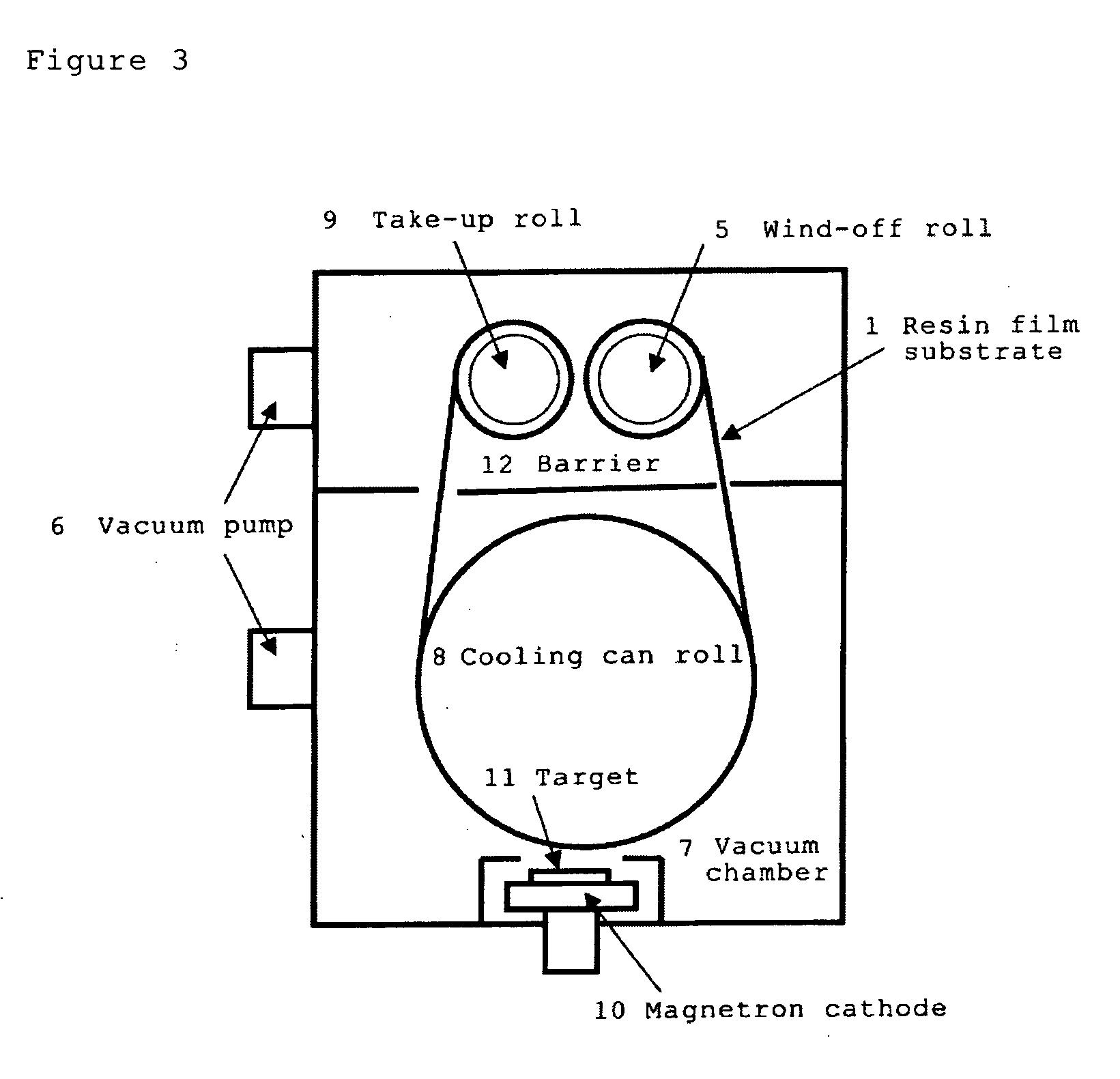
[0136]Using a reel-equipped sputtering unit illustrated in FIG. 3, a metal carbide layer was formed on a resin film substrate having a heat resistance of 200° C. or higher. First, a target 11 providing a layer material was set on a magnetron cathode 10 which was set in such a manner to face to the surface of a cooling can roll 8. A film transfer section comprising a wind-off roll 5, a cooling can roll 8, a take-up roll 9, and the like, was isolated from the magnetron cathode 10 with a diaphragm 12. Next, a rolled resin film substrate 1 was set on the wind-off roll 5.

[0137]As the resin film substrate, a polyimide (PI) film, having a thickness of 75 μm and a surface with a fine concavity and convexity structure with an arithmetic average height Ra of 0.5 μm obtained by applying a surface treatment by sand blasting, was used. This polyimide (PI) film was sufficiently dried by heating at a temperature of 200° C. or higher before sputtering.

[0138]Next, contents in a vacuum chamber 7 were...

example 2

[0147]A heat-resistant light-shading film was prepared under the same conditions as in Example 1 except that only thickness of the titanium carbide layer was changed to 110 nm by varying film transfer speed in sputtering. Kind of the target material, type, thickness and surface roughness of the polyimide were same to those in Example 1. Degree of vacuum in the vacuum chamber attained before starting the sputtering was 6×10⁻⁵ Pa or less. Content of carbon in the light-shading layer was same to that in Example 1. Content of oxygen in the layer quantitatively analyzed by an XPS was 0.4 in atomic number ratio O / Me. From the X-ray diffraction measurement, it was found that the layer was a TiC layer having a superior crystallinity. Cross-sectional observation by a TEM also revealed that it was a dense layer composed of crystal grains.

[0148]Evaluations (optical characteristics and heat resistance) of the resultant heat-resistant light-shading film were carried out by the same procedures an...

example 3

[0151]A heat-resistant light-shading film was prepared under the same conditions as in Example 2 except that the degree of vacuum in the vacuum chamber attained before starting the sputtering was 8×10⁻⁴ Pa and that a titanium carbide layers having a thickness of 550 nm was formed on the both sides of the film substrate by repeating the sputtering 5 times on the film substrate, among the sputtering conditions in Example 2. Kind of the target material, type, thickness and surface roughness of the polyimide were same to those in Example 1.

[0152]Evaluations (optical characteristics and heat resistance) of the resultant heat-resistant light-shading film were carried out by the same procedures and under the same conditions to those in Example 1. Film surface temperature in the sputtering time of the titanium carbide layer was measured through the inspection window of quartz glass in the reel-equipped sputtering unit by the infrared radiation thermometer in the same manner as in Example 1....


PUM

PropertyMeasurementUnit
Temperatureaaaaaaaaaa
Lengthaaaaaaaaaa

Abstract

A heat-resistant light-shading film having high light shading capacity, high heat resistance, high sliding characteristics, low surface gloss and high electroconductivity, and useful for optical device parts such as shutter blades or diaphragm blades for diaphragm blades of lens shutter and the like for digital cameras and digital video cameras and diaphragm blades of light intensity adjusting device for projectors, and a method for producing the same.The heat-resistant light-shading film is a film comprising a resin film substrate (A) having a heat resistance of 155° C. or higher and a light-shading layer (B) of crystalline metal carbide film (MeC) formed on one side or both sides of the resin film substrate (A), characterized in that the light-shading layer (B) has a thickness of 100 nm or more and a surface roughness of 0.1 to 2.1 μm (arithmetic average height Ra), and content of carbon element (C) in the metal carbide film (MeC) is 0.3 or more in atomic number ratio to the total metal elements (Me).

Description

BACKGROUND OF THE INVENTION[0001]1. Field of the Invention[0002]The present invention relates to a heat-resistant light-shading film and method for producing the film, and diaphragm or light intensity adjusting device using the film, in more detail, a heat-resistant light-shading film having high light shading capacity, high heat resistance, high sliding characteristics, low surface gloss and high electroconductivity, which are used as optical device parts, e.g. shutter blade or diaphragm blades for diaphragm or lens shutter for digital cameras and digital video cameras and the like, fixed diaphragm in lens unit for in-vehicle monitors, and diaphragm blades of light intensity adjusting device for projectors; method for producing the film; and diaphragm or light intensity adjusting device using the film.[0003]2. Description of the Prior Art[0004]Recently, shutter blades or diaphragm blades for cameras have been required to be lighter and have higher sliding characteristics as shutter...

Claims


Application Information

Patent Timeline
IPC IPC(8): B32B33/00B32B15/08C23C14/14
CPCB32B38/0008B32B2037/243B32B2307/308B32B2307/408B32B2309/02Y10T428/24355B32B2551/00C23C14/0635C23C14/3414G02B5/005Y10T428/265B32B2309/105
Inventor ABE, YOSHIYUKIONO, KATSUSHITSUKAKOSHI, YUKIO
Owner SUMITOMO METAL MINING CO LTD
Learn More