Method of producing a ceramic sintered body

a technology of ceramic and sintered body, which is applied in the field of ceramic laminated sintered body, can solve the problems of reducing generation efficiency after repeating, and achieve the effects of imparting structural strength, preventing oxidation and corrosion of conductive interconnectors, and imparting structural strength

Inactive Publication Date: 2008-10-09
NGK INSULATORS LTD
View PDF9 Cites 4 Cited by
  • Summary
  • Abstract
  • Description
  • Claims
  • Application Information

AI Technical Summary

Benefits of technology

[0019]An object of a first aspect of the present invention is to apply a laminated sintered body of ceramic porous and dense bodies on an electrochemical cell, and to improve the operational efficiency of the cell and to prevent the deterioration of the cell after the activation and termination of operation is repeated so as to prevent the reduction of the operational efficiency of the cell.
[0044]According to the third aspect of the present invention, the conductive interconnector can be a self-standing structure, to prevent the reduction of operational efficiency due to the oxidation and corrosion of the interconnector and to reduce the internal resistance in the interconnector as possible so that the loss of electric current can be lowered.

Problems solved by technology

That is, the air tightness of the solid electrolyte film having a large area and small thickness is reduced to a value lower than a specific value, it is proved that the cell is deteriorated to result in a considerable reduction of generation efficiency after repeating activation and termination of the operation of the cell.

Method used


Image

  • Method of producing a ceramic sintered body
  • Method of producing a ceramic sintered body
  • Method of producing a ceramic sintered body

Examples


examples

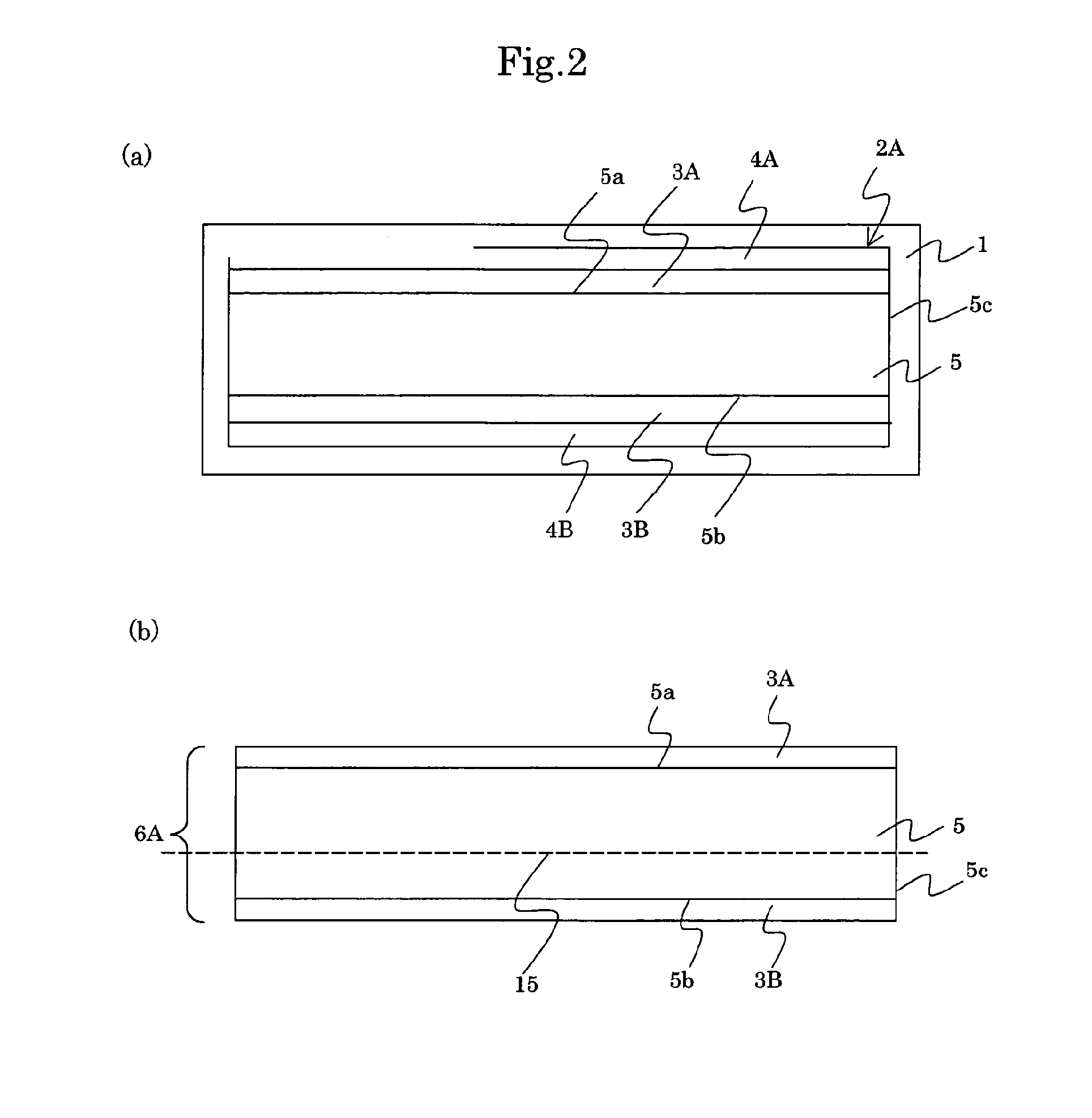
Experiment “A′” According to the Second Aspect of the Present Invention

Production of a Pressure Molded Body 6

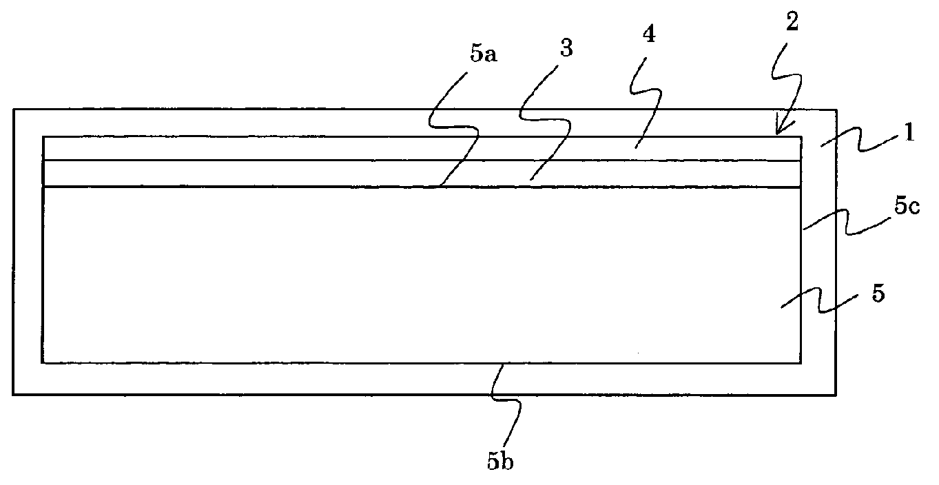
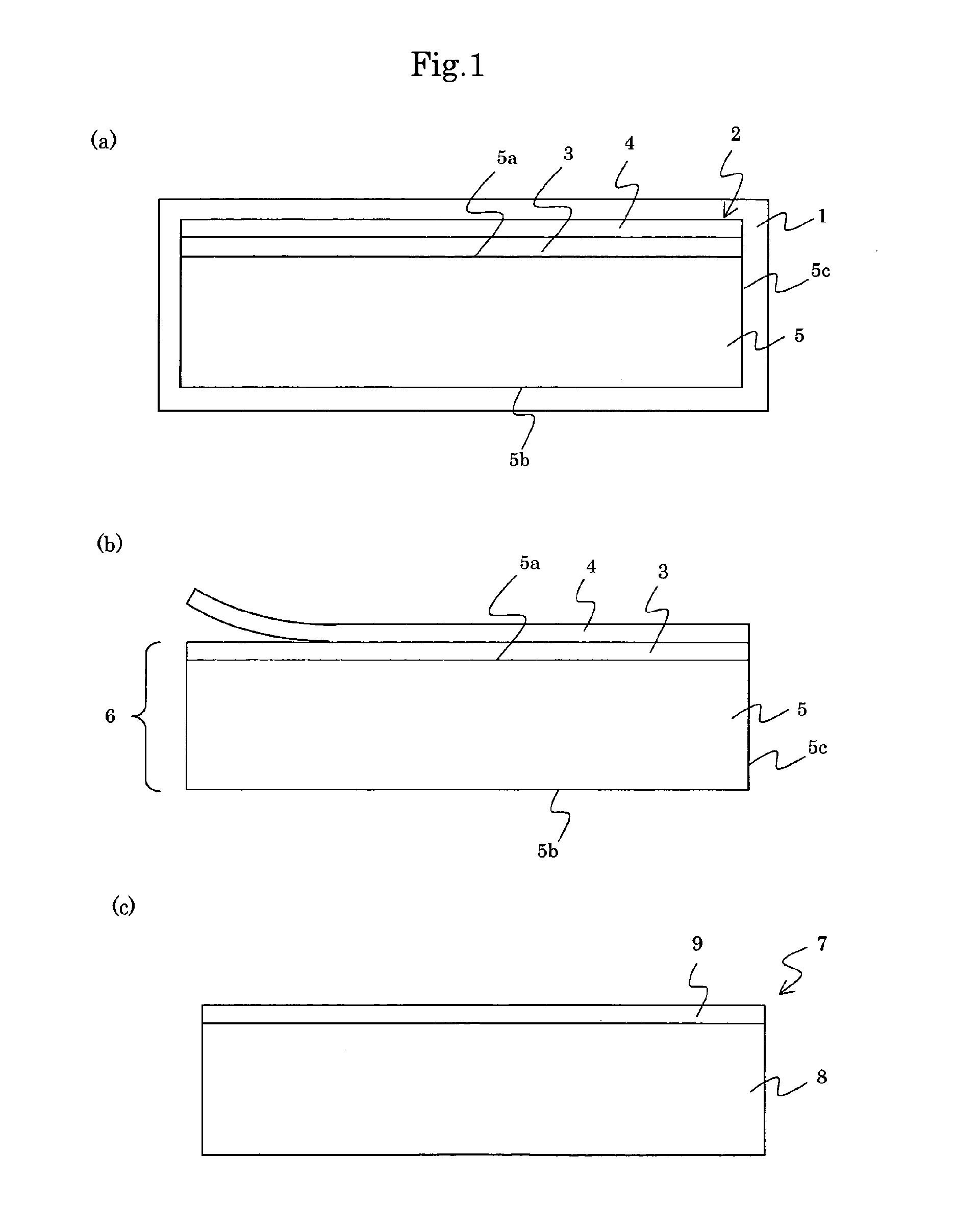
[0109]Alumina balls each having a diameter of 10 mm were contained in a container of nylon. 100 weight parts of 3 mole percent yttria stabilized zirconia, 20 weight parts of toluene, 11 weight parts of ethanol and 2 weight parts of butanol as solvents were added and mixed in a ball mill at a revolution speed of 60 rpm. After that, 8 weight parts of polyvinylbutyral, 3 weight parts of dibutyl phthalate, 26 weight parts of toluene and 15 weight parts of ethanol were added to the mixture, and further mixed in the ball mill. The thus obtained slurry was shaped as a sheet by doctor blade method on a sheet (thickness of 100 μm resin sheet 4) of polyethylene terephthalate. The green sheet 3 for dense body having a width of 50 mm and thickness of 20 μm of 3 mole percent yttria stabilized zirconia (for a solid electrolyte film) was produced on the resin sheet 4.

[0110]Further, an organ...


PUM

PropertyMeasurementUnit
Thicknessaaaaaaaaaa
Thicknessaaaaaaaaaa
Pressureaaaaaaaaaa

Abstract

A method of producing a laminated body having a ceramic porous body having a thickness of 300 μm or larger and a ceramic dense body having a thickness of 25 μm or smaller. A green body for the porous body and a green body for the dense body are laminated to obtain a laminate, which is then subjected to pressure molding by cold isostatic pressing to obtain a pressure molded body. The pressure molded body is sintered to obtain a laminated sintered body. By reducing the leakage rate of helium gas of the laminated sintered body to 10−6 Pa˜m3 / s or lower, the operational efficiency of the cell can be improved, and the deterioration of the cell can be prevented to improve an output after the cell is subjected to initiation and termination cycle tests of operation.

Description

CROSS REFERENCE TO RELATED APPLICATIONS[0001]This application is division of U.S. application Ser. No. 10 / 803,221, having a filing date of Mar. 18, 2004, which in turn is a continuation of International Application No. PCT / JP02 / 09913, having an international filing date of Sep. 26, 2002, which designated the United States, the entireties of which are incorporated herein by reference.[0002]This application also claims the benefit of Japanese Application No. 2001-292882, filed Sep. 26, 2001, and Japanese Application No. 2001-297325, filed Sep. 27, 2001, the entireties of which are incorporated herein by reference.FIELD OF THE INVENTION[0003]The present invention relates to a ceramic laminated sintered body, a method of producing the same, an electrochemical cell, a conductive interconnector for electrochemical cell and an electrochemical device.BACKGROUND OF THE INVENTION[0004]Solid oxide fuel cells are generally divided into two categories; planar and tubular types. In planar type so...

Claims


Application Information

Patent Timeline
IPC IPC(8): H01M8/02
CPCB32B18/00B32B2311/06B32B2311/09B32B2311/22B32B2315/02C04B35/01C04B35/016C04B35/42C04B35/488C04B2235/3213C04B2235/3217C04B2235/3227C04B2235/3229C04B2235/3241C04B2235/3244C04B2235/3272C04B2235/3275C04B2235/3279C04B2235/405C04B2235/77C04B2235/80C04B2237/34C04B2237/345C04B2237/348C04B2237/405C04B2237/408C04B2237/704H01M8/0219H01M8/0228H01M8/0236H01M8/0245H01M8/1206H01M8/1253H01M8/126Y02E60/521Y02E60/525H01M8/1231Y02E60/50Y02P70/50
Inventor ITO, SHIGENORIOKUMURA, KIYOSHISAKAI, HIROAKI
Owner NGK INSULATORS LTD
Why Eureka
Try Eureka