
Composite components with integral protective casings

a technology of composite components and protective casings, applied in the field of structural composite components, can solve the problems of low densities of polymer composites, harsh environmental conditions during use of rockets, missiles and other similar airborne structures that move through the air at very high speeds, and limit the feasibility of using materials such as metals and metal alloys

Inactive Publication Date: 2008-10-02
ADVANCED CERAMICS
View PDF13 Cites 17 Cited by
  • Summary
  • Abstract
  • Description
  • Claims
  • Application Information

AI Technical Summary

Benefits of technology

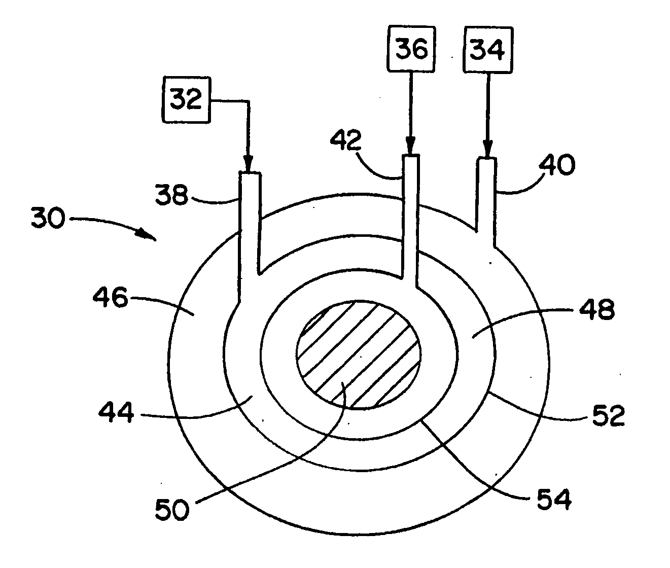
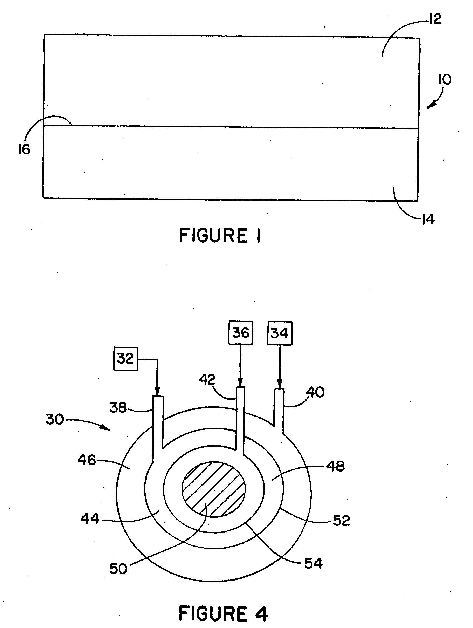
[0011]The present invention is directed to a durable composite structure that is lightweight and capable of withstanding elevated temperatures and / or pressures. More specifically, the present invention relates to methods and compositions for fabricating multiple layer composite parts that avoid the need for secondary manufacturing operations, including bonding operations, and structural defects associated with parts assembled by such operations. Two or more compositions may be molded and co-cured to provide a multiple layer composite component having integrally formed, securely bonded layers that generally will not be subject to delamination.
[0012]In one aspect, at least one of the layers includes a polymer composition. The polymer composition provides a durable, lightweight support structure for the composite part. The polymer composition may be selected from aerospace-grade epoxies or other suitable epoxies, such as fiberglass and vinyl ester. Fibrous material may be included in the composition to enhance the strength and fracture toughness of the resulting layer.
[0013]The composite part also includes a protective layer for surfaces of the polymer composition layer that may be exposed to elevated temperatures. The layer is disposed between the exposed surface and the deteriorative environment and is selected to be effective for shielding the structural support layer from the detrimental effects of heat and fire. The insulating layer may include ceramic compositions and preferably may have thermal conductivities of up to about 10 watts per meter-Kelvin (W / m-K) and more preferably no more than about 3 W / m-K. Suitable compositions include Si3N4, SiC, ZrC, Si—O—N (sialons), magnesium aluminosilicate (cordierite), fused silica and mixtures thereof. The ceramic composition may be a green ceramic, at least partially sintered, or fully sintered. Fibrous material may be included in the composition to enhance the fracture toughness and insulating effect of the ceramic composition. The ceramic composition layer also may have a predetermined porosity to provide an increased insulating effect. Preferably, the porosity of the layer may be at least about 20 percent by volume and the pores may be internally disposed in the layer with diameters of between about 50 to about 100 μm. The insulating layer may provide protection against temperatures of at least about 1200° C. and even as great as 3500° C. or higher. The insulating layer also may provide a barrier that limits moisture migration.
[0014]In another aspect, a ceramic composition may be used in place of the polymer composition to provide structural support. The ceramic composition is selected to be lightweight and have sufficient strength and fracture toughness. The ceramic compositions preferably may have thermal conductivities of up to about 10 W / m-K and more preferably no more than about 3 W / m-K. Suitable compositions include Si3N4, SiC, ZrC, Si—O—N (sialons), magnesium aluminosilicate (cordierite), fused silica and mixtures thereof. The ceramic composition may be a green ceramic or may be at least partially sintered. Fibrous material may be included in the composition to enhance the fracture toughness and insulating effect of the ceramic composition.
[0017]One or more of the layers formed may provide structural support for the composite part, and one or more of the layers formed may provide protection for the structural layer against deteriorative environmental conditions such as elevated temperatures and pressures and fire. The structural support layer is formed of a thickness and density effective for providing support for and maintaining the structural integrity of the composite component. The protective layer is formed with a predetermined thickness effective for limiting the transfer of heat through the thickness of the layer. The protective layer also may include a predetermined degree of porosity to enhance its heat insulating effects.

Problems solved by technology

Rockets, missiles and other similar airborne structures that move through the air at very high speeds are subject to harsh environmental conditions during use.
Weight restrictions and cost concerns for such airborne structures, however, limit the feasibility of using materials such as metals and metal alloys.
Further, polymer composites have low densities, so that components fabricated of these materials are of lighter weight and well within applicable weight limits.
Although use of polymer composites for airborne structures can provide many advantages, material properties of such composites may restrict the use of polymer composites alone in high temperature and / or high-pressure applications.
Significantly, polymer composites are not fire resistant, and a thermally resistant material must be used in connection with polymer coating so that the polymer composite does not soften or ignite during use.
Additionally, the strength of the polymer composite alone often is not sufficient to withstand typical forces associated with missile systems and the like.
These post-bonded heat shields are often damaged during handling, and are rendered susceptible to debonding and moisture degradation over time.
As a result, the damaged heat shields typically must be repaired frequently over the life of the component, which is not only inefficient but costly, as well.

Method used


Image

  • Composite components with integral protective casings
  • Composite components with integral protective casings
  • Composite components with integral protective casings

Examples


example 1

Slurry Evaluation

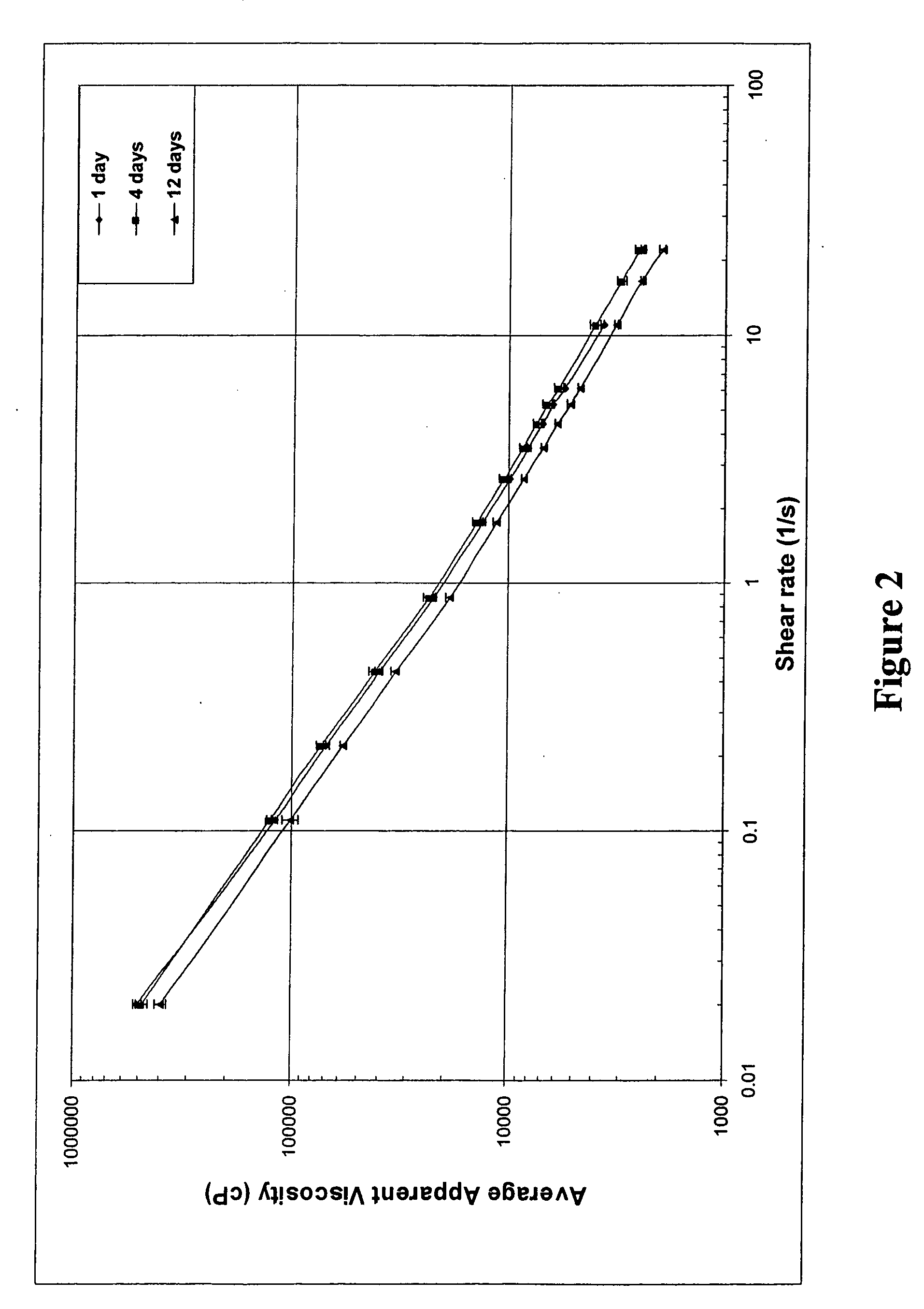
[0038]The following Si3N4 slurries were evaluated:[0039](1) Ceramic slurry made from a premixed blend of UBE E-5 and E-10 Si3N4 powder, commercially available from UBE Industries, Tokyo, Japan, and ceria-based sintering aids (53 vol % solids loading);[0040](2) Ceramic slurry made from a premixed blend of UBE E-5 and E-10 Si3N4 powder and added ceria-based sintering aids (50 vol % solids loading);[0041](3) Ceramic slurry of UBE E-5 and E-10 Si3N4 powder and aluminum nitride and alumina and yttria sintering aids (52.18 vol % solids loading);[0042](4) Ceramic slurry made from Stark M-11 Si3N4 powder, commercially available from H. C. Starck Inc., Newton, Mass., and alumina and yttria sintering aids, commercially available from Malakoff Industries, Malakoff, Tex., and Molycorp Inc., Mountain Pass, Calif., respectively (52 vol % solids loading);[0043](5) Ceramic slurry made from Stark M-11 Si3N4 powder and alumina and yttria sintering aids (42 vol % solids loading); and[...

example 2

CITRM of Composite Panels with Integral Heat Shields

[0048]Composite panels were fabricated using a CIRTM process. Epoxy resin and silicon nitride ceramic slurry were co-injected into a two-dimensional, 50% by volume porous fiber preforms to produce integral composite panels. A polysulfone layer was included as an intermediate layer for the epoxy resin and ceramic slurry to diffuse into and create a strong bond between the two layers after final curing. A 24-oz. S2 glass fabric was used as the preform. Initial co-injection tests were used to evaluate slurry rheology and whether the slurries were capable of being effectively co-injected with the polymer composite resins.

[0049]Once the co-injection process was complete, the composite panels were allowed to self-cure for several hours during the exothermic portion of the curing cycle. To accelerate the final stages of the endothermic curing cycle, the panels were placed in a 350° F. oven for 2 hours. The following 6″×6″ panels were prod...


PUM

PropertyMeasurementUnit
diametersaaaaaaaaaa
temperaturesaaaaaaaaaa

Abstract

Methods and compositions for fabricating composite parts including at least one structural material and at least one protective material that are integrally bonded without the use of secondary bonding operations. One or more of the materials forming the layers of the composite parts may be a ceramic composition with or without porosity and one or more of the materials may be a polymer composition. Methods including co-injection processes also are provided for fabricating multi-layered structures in which each layer serves a desired function while still being integrated into the overall structure.

Description

CROSS REFERENCE TO RELATED APPLICATIONS[0001]This application is a divisional of U.S. patent application Ser. No. 10 / 293,852, filed on Nov. 12, 2002, entitled “Composite Components with Integral Protective Casings,” which claims the benefit of U.S. Provisional Application No. 60 / 344,936, filed on Nov. 9, 2001, and entitled “Composite Casings with Integral Heating Shields”, now abandoned, both of which applications are incorporated herein by reference.[0002]The present invention was made with U.S. Government support under SBIR Grants #F04611-01-C-0058 and DASG60-02-P-0234 awarded by the Air Force and the Army, respectively. Accordingly, the U.S. Government may have certain rights in the invention described herein.FIELD OF THE INVENTION[0003]The present invention relates to structural composite components. More particularly, this invention relates to lightweight ceramic structures having integral insulating layers for thermal protection in high temperature applications, such as in tur...

Claims


Application Information

Patent Timeline
Patent Type & Authority Applications(United States)
IPC IPC(8): B29C45/16B64C1/00C04B35/581C04B35/584C04B35/80F42B10/46
CPCC04B35/581C04B35/584C04B35/62625C04B35/6263C04B35/6303C04B35/806Y10T428/24124C04B2235/3217C04B2235/3225C04B2235/3229C04B2235/80F42B10/46C04B35/82C04B35/80
Inventor VAIDYANATHAN, K. RANJIGREEN, CATHERINEGILLESPIE, JOHN W.YARLAGADDA, SHRIDHARARTZ, GREGORY J.
Owner ADVANCED CERAMICS
Learn More