Lithium cell

a lithium cell and preconditioning technology, applied in the direction of primary cell maintenance/service, secondary cell servicing/maintenance, non-aqueous electrolyte cells, etc., can solve the problems of reducing the efficiency of the cell, affecting the cell performance, and affecting the cell function, so as to improve the cell performance, improve the voltage profile, and improve the effect of energy outpu

Active Publication Date: 2008-09-25
DURACELL U S OPERATIONS
View PDF4 Cites 17 Cited by
  • Summary
  • Abstract
  • Description
  • Claims
  • Application Information

AI Technical Summary

Benefits of technology

[0024]In a principal aspect the invention is directed to mitigating the effect of the lithium passivation layer which develops on the surface of the lithium or lithium alloy anode. (All lithium cells which have exposed lithium metal or lithium metal alloy surfaces can develop a coating or passivation layer thereon, which can reduce the electrochemical reactivity of the lithium surface and increase the cell's internal resistance.) It has been determined that the deleterious effect of the lithium passivation layer can be mitigated by subjecting the Li / FeS2 cell to a preconditioning (predischarge) protocol after the cell is assembled fresh but before it is released for commercial sale. (The term “fresh” or “fresh cell” as used herein is intended to refer to cells that have been manufactured but not yet released for commercial use.)
[0028]It has been determined that when a fresh Li / FeS2 cell is subjected to such preconditioning protocol of the invention there is a marked improvement in cell performance. That is, the cell will maintain a higher voltage profile at a given discharge current than if the cell was not subjected to the preconditioning protocol of the invention. This in turn results in a higher energy output for the Li / FeS2 cell which was subjected to the preconditioning protocol of the invention. The improved performance can be expected regardless of cell shape or configuration (e.g. button cell or wound cylindrical cell).
[0029]The preconditioning (predischarge) protocol of the invention to which a fresh Li / FeS2 cell is subjected is believed to have a mitigating effect on the lithium passivation layer which develops on the surface of the lithium anode. It is believed that the preconditioning (predischarge) protocol of the invention stabilizes the lithium passivation layer and may also alter its chemistry. This in turn can reduce the resistance of the lithium passivation layer and reduces the cell's internal resistance to improve cell performance. The preconditioning protocol, which involves at least one cell storage period (step rest) at above ambient temperature after a discharge step involving at least one pulsed discharge cycle, may also help to remove impurities from the electrolyte and cathode, thus improving the effectiveness of the electrolyte and cathode material.
[0033]A desirable electrolyte mixture for the Li / FeS2 cell of the invention has been determined to comprise the lithium salt lithium trifluoromethane sulfonate chemical formula LiCF3SO3 (LiTFS) and / or lithium bistrifluoromethylsulfonyl imide chemical formula Li(CF3SO2)2N (LiTFSI) dissolved in an organic solvent mixture comprising dimethoxyethane (DME), ethylene carbonate (EC), and propylene carbonate (PC). A preferred electrolyte mixture has been determined to be an electrolyte solution comprising between about 0.3 molar to 0.6 molar (0.3 to 0.6 mol / liter) LiCF3SO3 (LiTFS) salt and 0.3 molar to 0.6 molar (0.3 to 0.6 mol / liter) Li(CF3SO2)2N (LiTFSI) salt, 0.25 wt % LiClO4 and 0.5 wt % elemental iodine dissolved in an organic solvent mixture comprising between about 75 and 95 wt % dimethoxyethane (DME), between 2 and 10 wt. % ethylene carbonate (EC), and between about 3 and 15 wt. % propylene carbonate (PC). The LiClO4 is optional but its inclusion in the electrolyte is desirable because it functions as an anticorrosion inhibitor for the aluminum or aluminum alloy grid or substrate onto which the cathode coating comprising iron disulfide is coated. Elemental iodine (I2) is desirably added to such electrolyte mixture for Li / FeS2 cells. The desirability of adding elemental iodine to nonaqueous electrolyte mixtures for Li / FeS2 cells is disclosed in commonly assigned U.S. patent application Ser. No. 11 / 650,405, filed Jan. 5, 2007. The addition of the iodine has been determined to mitigate the deleterious effect of the lithium passivation layer which accumulates on the surface of the lithium anode. It is believed the presence of elemental iodine in the electrolyte helps to mitigate the effect of the lithium passivation layer on the surface of the lithium anode by altering the chemistry of the lithium passivation layer, that is, to make it less resistive. Thus both the above referenced preconditioning protocol of the invention to which a fresh cell is subjected together with inclusion of elemental iodine in the electrolyte both appear to have a compounding effect of mitigating the effect of the lithium passivation layer on the surface of the lithium anode. This in turn improves cell performance. The addition of elemental iodine to the nonaqueous electrolyte also resolves or mitigates the problem of voltage delay (voltage drop) which may otherwise occur or be more significant at the onset of a fresh discharge period of a Li / FeS2 cell employing electrolyte comprising cyclic organic carbonate solvents such as ethylene carbonate (EC) and / or propylene carbonate (PC).
[0035]If the cathode slurry comprising FeS2 powder and conductive carbon is coated onto a sheet of aluminum substrate (cathode current collector), the presence of elemental iodine in the electrolyte can also retard the rate of aluminum surface corrosion which can develop during normal usage or storage of the Li / FeS2 cell.

Problems solved by technology

This is because undesirable oxidation / reduction reactions between the electrolyte and electrode materials (either discharged or undischarged) could thereby gradually contaminate the electrolyte and reduce its effectiveness or result in excessive gassing.
This in turn can result in a catastrophic cell failure.
Thus, it should be evident from the above representative references that the choice of a particular organic solvent or mixture of different organic solvents for use in conjunction with any one or more lithium salts to produce a suitable electrolyte for the Li / FeS2 cell is challenging.
But rather the problems associated with such cells using an electrolyte formed with just any combination of lithium salt and organic solvent is that the problems encountered will likely be very substantial, thus making the cell impractical for commercial usage.
However, dioxolane has the disadvantage of cost and handling.
However, experiments with such electrolytes and electrolyte solvent systems, that is, comprising ethylene carbonate (EC) and propylene carbonate (PC) solvents, while effective in Li / MnO2 cells result in deficiencies when employed, per se, in the context of the Li / FeS2 cell.
One of the difficulties is that such ethylene carbonate / propylene carbonate electrolyte solvent mixtures tend to cause or exacerbate the problem of lithium surface passivation, which normally occurs at least to a degree during the discharge life of the Li / FeS2 cell.
Such surface layers, some more debilitating than others, can reduce the rate of the electrochemical reaction involving the lithium anode metal during cell discharge, thus interfering with proper cell performance.
Another problem encountered with the use of ethylene carbonate / propylene carbonate electrolyte solvent mixtures for Li / FeS2 cells is that such solvents tend to cause or exacerbate the problem of initial voltage delay (voltage drop) which may occur typically during an initial phase or initial period of cell usage.
Such voltage drop, which can occur at the onset of a new period of cell usage, can reduce the running voltage of the cell for a brief period and thus interfere with attainment of expected consistent, reliable, cell performance.

Method used


Image

  • Lithium cell
  • Lithium cell
  • Lithium cell

Examples


example

Experimental Test Lithium Coin

Cells with Cathode Comprising FeS2

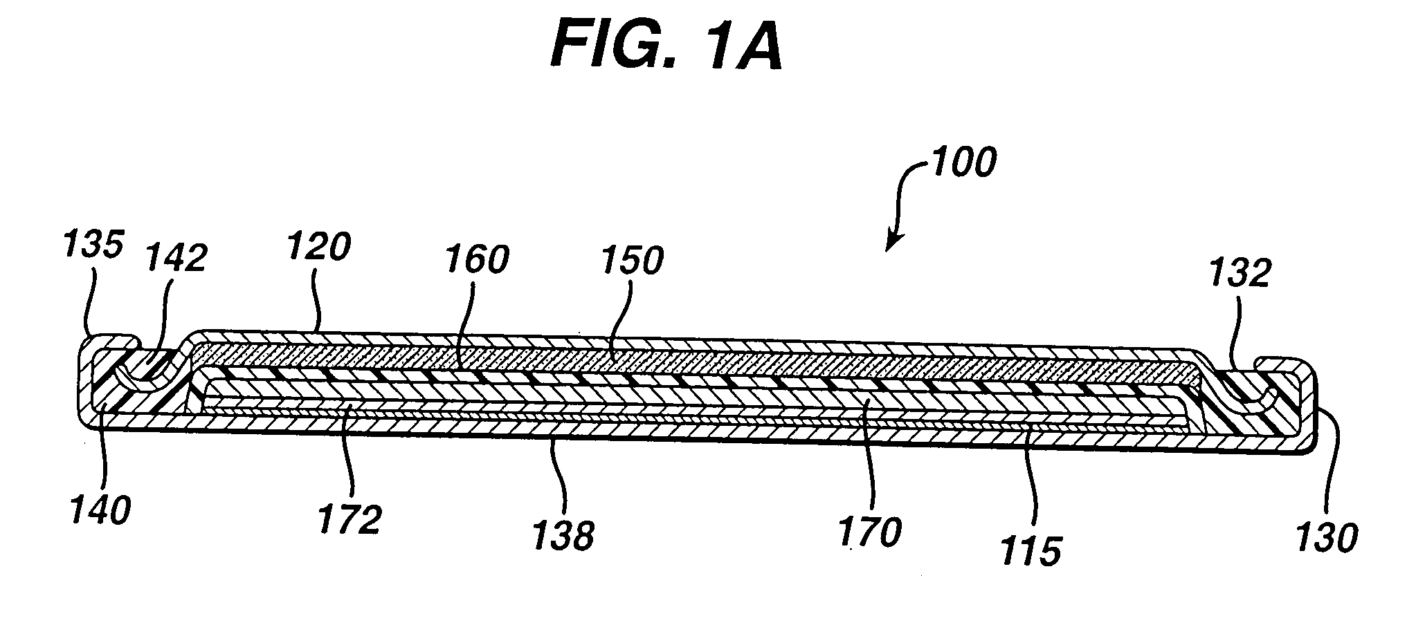
[0082]Experimental test Li / FeS2 coin cells 100 (FIG. 1A) were prepared as follows:

Experimental Test Cell Assembly:

[0083]A coin shaped cathode housing 130 of nickel plated steel and a coin shaped anode housing (cover) 120 of nickel plated steel is formed of a similar configuration shown in FIG. 1A. The finished cell 100 had an overall diameter of about 25 mm and a thickness of about 3 mm. The weight of FeS2 in the cathode housing 130 was 0.125 g. The lithium was in electrochemical excess.

[0084]In forming each cell 100, an Arbor press with a 0.780-inch die was used to punch out two stainless steel grids (316L-SS EXMET expanded metal foil). One stainless steel grid was centered inside of coin cell cathode housing 130 forming cathode current collector sheet 115. The other stainless steel grid (not shown) was resistance welded to the inside surface of closed end of the anode housing (cover) 120. The grids were welded to the...


PUM


Abstract

A primary cell having an anode comprising lithium and a cathode comprising iron disulfide (FeS2) and carbon particles. The cell can be in the configuration of a coin cell or the anode and cathode can be spirally wound with separator therebetween and inserted into the cell casing with electrolyte then added. The electrolyte comprises a lithium salt dissolved in a nonaqueous solvent mixture which may include an organic cyclic carbonate such as ethylene carbonate and propylene carbon. The cell after assembly is subjected to a two step preconditioning (prediscahrge) protocol involving at least two distinct discharge steps having at lease one cycle of pulsed current drain in each step and at least one rest period (step rest) between said two steps, wherein said step rest period is carried out for a period of time at above ambient temperature. The preconditioning improves cell performance.

Description

FIELD OF THE INVENTION[0001]The invention relates to a method for preconditioning a primary cell having an anode comprising lithium and a cathode comprising iron disulfide. A fresh cell is subjected to a pulsed discharge step followed by step rest at elevated temperature, preferably followed by a second pulsed discharge step, thereby preconditioning the cell and improving cell performance.BACKGROUND[0002]Primary (non-rechargeable) electrochemical cells having an anode of lithium are known and are in widespread commercial use. The anode is comprised essentially of lithium metal. Such cells typically have a cathode comprising manganese dioxide, and electrolyte comprising a lithium salt such as lithium trifluoromethane sulfonate (LiCF3SO3) dissolved in a nonaqueous solvent. The cells are referenced in the art as primary lithium cells (primary Li / MnO2 cells) and are generally not intended to be rechargeable, that is, they are intended to be discarded after they have been discharged. Alt...

Claims


Application Information

Patent Timeline
IPC IPC(8): H01M10/44H01M4/58
CPCH01M4/382H01M4/5815H01M6/164H01M6/5088H01M6/168H01M6/50H01M6/166
Inventor ISSAEV, NIKOLAI N.POZIN, MICHAEL
Owner DURACELL U S OPERATIONS
Why Eureka
Try Eureka