
Process for dispersing nanocatalysts into petroleum-bearing formations

a technology of nanocatalysts and petroleum-bearing formations, which is applied in the direction of fluid removal, insulation, borehole/well accessories, etc., can solve the problems of large coke formation, sharp reduction of the value of oil to refiners, and difficult and expensive reprocessing of resources into saleable products, etc., to reduce the viscosity of heavy crude oil, reduce the viscosity, and reduce the impurities of sulfur

Inactive Publication Date: 2008-09-11
WORLD ENERGY SYST
View PDF31 Cites 50 Cited by
  • Summary
  • Abstract
  • Description
  • Claims
  • Application Information

AI Technical Summary

Benefits of technology

[0013]In another example, the steam is generated by combusting oxygen gas and hydrogen gas within the steam generator. The oxygen gas and the hydrogen gas may each be transferred from outside of the formation, through a borehole, and into the formation. In another example, the steam is generated by combusting oxygen gas and a hydrocarbon gas within the steam generator. The oxygen gas and the hydrocarbon gas may each be transferred from outside of the formation, through a borehole, and into the formation. The hydrocarbon gas may contain methane. In other examples, the heavy crude oil and the catalytic material may be exposed to a carrier gas, such as carbon dioxide, to reduce viscosity. Carbon dioxide is soluble in the heavy crude oil thereby reduces the viscosity of the heavy crude oil within the formation. The carbon dioxide may be transferred from outside of the formation, through a borehole, and into the formation. In other examples, the recovered lighter oil products contain a lower concentration of a sulfur impurity than the heavy crude oil. The lighter oil products may contain about 30% by weight less sulfur impurities than the heavy crude oil, preferably, about 50% by weight less sulfur impurities than the heavy crude oil.

Problems solved by technology

As a result, these resources are difficult and expensive to refine into saleable products.
Pyrolysis occurs when oil thermally cracks at temperatures greater than about 650° F. Although pyrolysis reduces the viscosity of oil, sometimes dramatically, it often results in the formation of large quantities of coke.
This thermal reaction also causes a desirable increase in the API gravity, but it has little effect on the sulfur and tends to raise the total acid number, which sharply reduces the value of the oil to refiners.
Delayed coking is not well-suited for in situ upgrading because of the high temperatures (e.g., about 900° F.-1,250° F.) and the short reaction times (e.g., about 2-3 hours) required to complete the process.
However, the stumbling block that prevents the application of these solutions to in situ upgrading is the lack of technique or method to inject the appropriate catalysts (e.g., nanoparticles) and then disperse them throughout a portion of the target reservoir.
Although this solution is beneficial for many applications, it is not suitable for introducing and distributing nanocatalysts in an oil-bearing formation.

Method used


Image

  • Process for dispersing nanocatalysts into petroleum-bearing formations
  • Process for dispersing nanocatalysts into petroleum-bearing formations
  • Process for dispersing nanocatalysts into petroleum-bearing formations

Examples


Embodiment Construction

[0035]Although the following detailed description contains many specific details for purposes of illustration, anyone of ordinary skill in the art will appreciate that many variations and alterations to the following details are within the scope of the invention. Accordingly, the exemplary embodiments of the invention described below are set forth without any loss of generality to, and without imposing limitations thereon, the present invention.

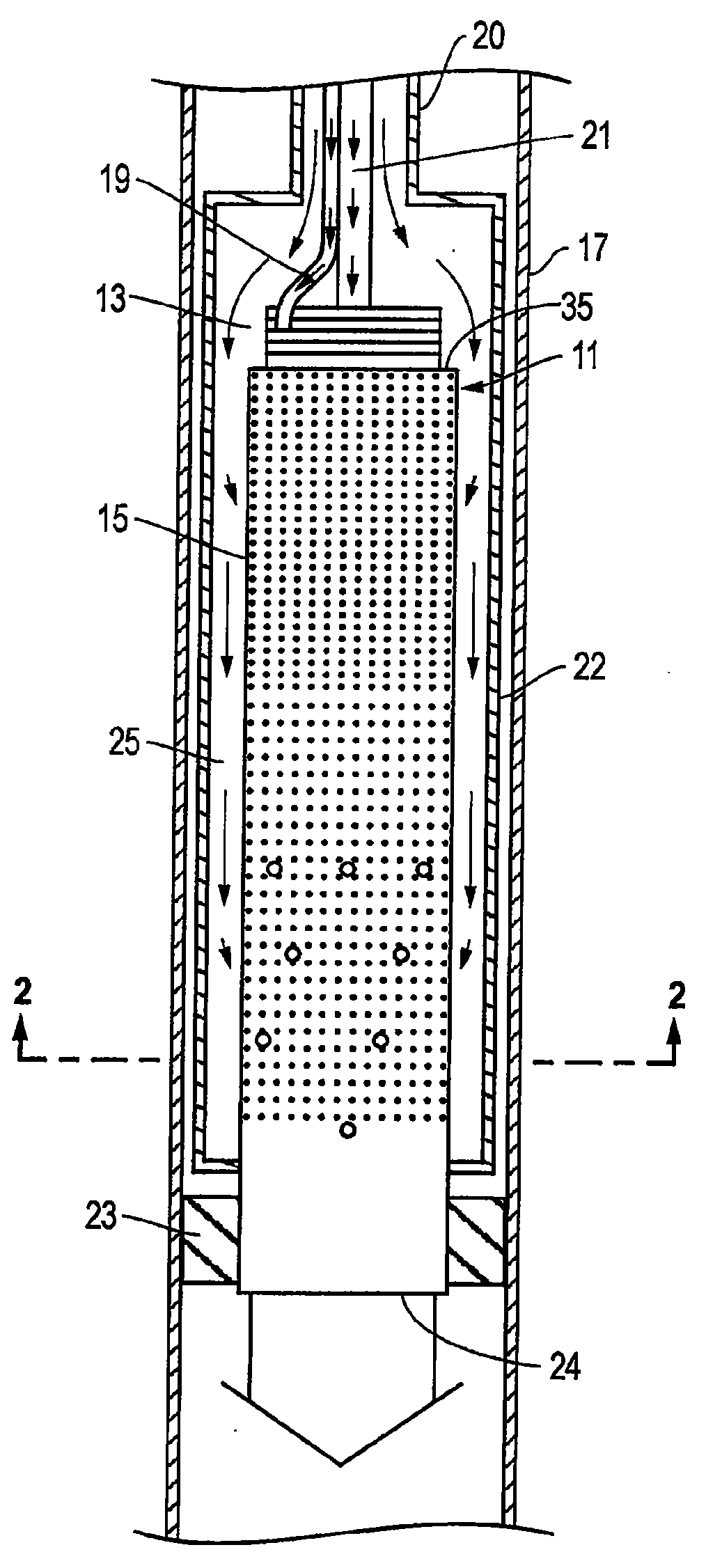
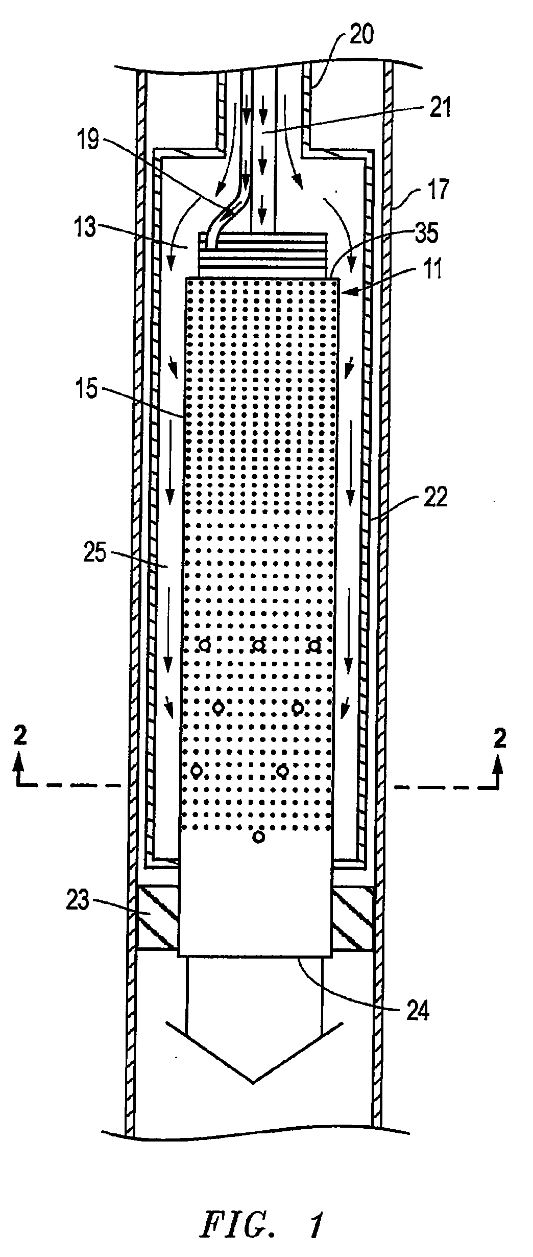
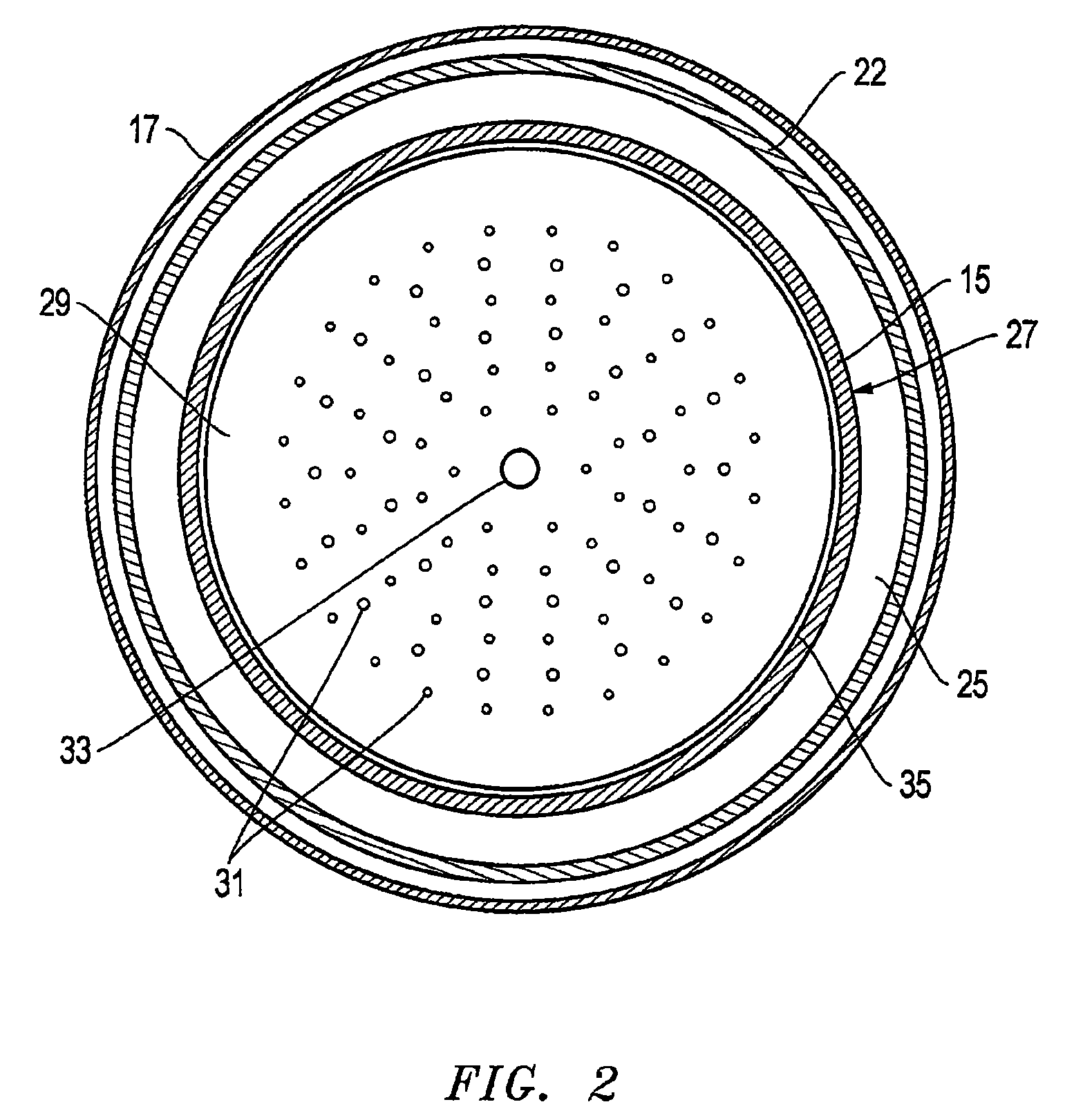
[0036]FIG. 1 depicts a downhole burner 11 positioned in a well according to an embodiment of the invention. The well may contain various wellbore configurations including, for example, vertical, horizontal, SAGD, or various combinations thereof. One skilled in the art will recognize that the burner also functions as a heater for heating the fluids entering the formation. A casing 17 and a packer 23 are shown in cross-section taken along the longitudinal axis of casing 17. Downhole burner 11 includes an injector 13 and a cooling liner 15 conta...


PUM


Abstract

Embodiments of the invention provide methods for recovering petroleum products from a formation by distributing nanocatalysts into the formation and heating the heavy crude oil therein. In one embodiment, a method is provided which includes flowing a catalytic material containing the nanocatalyst into the formation containing the heavy crude oil, exposing the heavy crude oil and the catalytic material to a reducing agent (e.g., H2), positioning a steam generator within the formation, generating and releasing steam from the steam generator to heat the heavy crude oil containing the catalytic material, forming lighter oil products within the formation, and extracting the lighter oil products from the formation. In another embodiment, a method is provided which includes exposing the heavy crude oil and the catalytic material to an oxidizing agent (e.g., O2). The nanocatalyst may contain cobalt, iron, nickel, molybdenum, chromium, tungsten, titanium, oxides thereof, alloys thereof, derivatives thereof, or combinations thereof.

Description

CROSS-REFERENCE TO RELATED APPLICATIONS[0001]This patent application claims benefit to U.S. Ser. No. 60 / 885,442, filed Jan. 18, 2007, and is a continuation-in-part of U.S. Ser. No. 11 / 868,707, filed Oct. 8, 2007, which claims benefit of U.S. Ser. No. 60 / 850,181, filed Oct. 9, 2006, U.S. Ser. No. 60 / 857,073, filed Nov. 6, 2006, and U.S. Ser. No. 60 / 885,442, filed Jan. 18, 2007, which are herein incorporated by reference in their entirety.BACKGROUND OF THE INVENTION[0002]1. Field of the Invention[0003]Embodiments of the invention relates in general to improving the performance of petroleum-bearing formations and, in particular, to an improved system, method, and apparatus for distributing nanocatalysts in petroleum-bearing formations.[0004]2. Description of the Related Art[0005]Vast quantities of heavy oil and bitumen are found in Canada, Venezuela, and the United States. These resources of heavy oil and bitumen are typically characterized by having low specific gravities (0-18° API),...

Claims


Application Information

Patent Timeline
IPC IPC(8): E21B43/22
CPCE21B36/02E21B43/164E21B43/168E21B43/24Y10S977/902E21B43/243B82Y99/00E21B43/16E21B43/2405
Inventor LANGDON, JOHN E.WARE, CHARLES H.
Owner WORLD ENERGY SYST
Learn More