
Composite wires for coating substrates and methods of use

a technology of composite wires and substrates, applied in the direction of other chemical processes, soldering apparatus, manufacturing tools, etc., can solve the problems of premature coating failure, accelerated wear of coatings, and easy corrosion of coatings, so as to improve the bonding of coatings, increase wear resistance, and increase metal binder hardness

Active Publication Date: 2008-05-01
INTEGRATED GLOBAL SERVICES
View PDF9 Cites 16 Cited by
  • Summary
  • Abstract
  • Description
  • Claims
  • Application Information

AI Technical Summary

Benefits of technology

The present invention provides a composite wire for producing a wear-resistant and corrosion-resistant coating on a substrate through thermal spraying, spray and fuse, or welding techniques. The coating exhibits good hardness, toughness, and bonding characteristics, and is particularly well-suited for high-temperature erosion-corrosion environments. The composite wire has an outer sheath made of metal or alloy and an inner core containing boron carbide and chrome carbide. The combination of chrome carbide and boron carbide in the inner core provides improved wear resistance, increased metal binder hardness, improved bonding of the coating to the substrate, and inhibits oxide formation. The outer sheath can be made of various metals or alloys, which, when combined with the inner core powder, result in coatings with superior physical properties over conventional coatings. The method of forming a coating on a substrate involves using the composite wire and the substrate in conjunction with thermal spraying, spray and fuse, or welding techniques.

Problems solved by technology

The metal components of the cored wires used to form the coatings disclosed in both U.S. Pat. Nos. 6,156,443 (Dallaire, et al.) and 5,837,326 (Dallaire, et al.) are not highly alloyed, and consequently the coatings tend to be susceptible to corrosion attack in certain high temperature corrosive conditions, such as in boiler applications.
For example, coatings with iron-based binder alloys, such as Armacor M™, exhibit extensive binder-material corrosion in boiler conditions, resulting in accelerated wear of the coatings.
The consequent weakening of the bonds can also lead to premature coating failure due to complete spalling of the protective layer.
Furthermore, the magnetic characteristics of these coatings prevent thickness measurements using standard equipment, such as Elcometers.
However, as with other conventional composite wires, in high-temperature corrosive environments, the wear resistant coatings may experience accelerated wear.

Method used


Image

  • Composite wires for coating substrates and methods of use
  • Composite wires for coating substrates and methods of use
  • Composite wires for coating substrates and methods of use

Examples


example 1

[0027]A composite wire of the present invention was formed with an outer sheath comprising of INCONEL® alloy 625 and an inner core comprising a substantially equivalent mixture of chrome carbide and boron carbide. INCONEL® alloy 625 is a product of the Special Metals Corporation and contains 0.1% C, 0.5% Mn, 5.0% Fe, 0.02% P, 0.015% S, 0.5% Si, 0.5% Cu, 58% min Ni, 0.4% Al, 0.4% Ti 20.0%-23.0% Cr, 3.15%-4.15% Nb+Ta, 8.0%010.0% Mo. This composite wire provided coatings with good toughness characteristics, low oxides, and good wear characteristics due to the novel carbide formulation of the inner core. In addition, there was an increase in the hardness of the metal binder due to the boron content. The coatings also exhibited good bonding characteristics. The following table illustrates the improved wear resistance of a coatings deposited by a composite wire of the present invention (row 3 and row 4) compared to the wear resistance of other coatings:

ASTM G65 Wear Test (15 Minutes)

[0028...

example 2

[0031]To illustrate bond strength, clean, bright smooth stainless steel coupons were coated, without any surface roughness, to establish how thick a coating could be sprayed before spalling occurred (i.e., bond failure). The first coupon was arc sprayed with pure alloy 625 and the second coupon was sprayed with a composite wire comprising an alloy 625 outer sheath and an inner core comprising 40% by weight boron carbide and 60% by weight chromium carbide. The first coupon exhibited Composite Wires For Coating Substrates And Methods of Use delamination at 300 μm, whereas the coating applied in accordance with the present invention was sprayed up to 2000 μm without any appearance of spalling.

example 3

[0032]Two clean steel coupons were coated, with grit-blasted surfaces; the first with pure alloy 625 and the second with a composite wire comprising an alloy 625 outer sheath and an inner core comprising 40% by weight boron carbide and 60% by weight chromium carbide. The coupons were mechanically damaged by cracking off the coating with a hammer and chisel. The pure 625 coating was peeled off of the first coupon as a continuous layer, while the composite wire sprayed coating could not be disjoined from the coupon. Rather, the composite wire sprayed coupon only sustained damage to the impact site, thus illustrating the high bond strength.

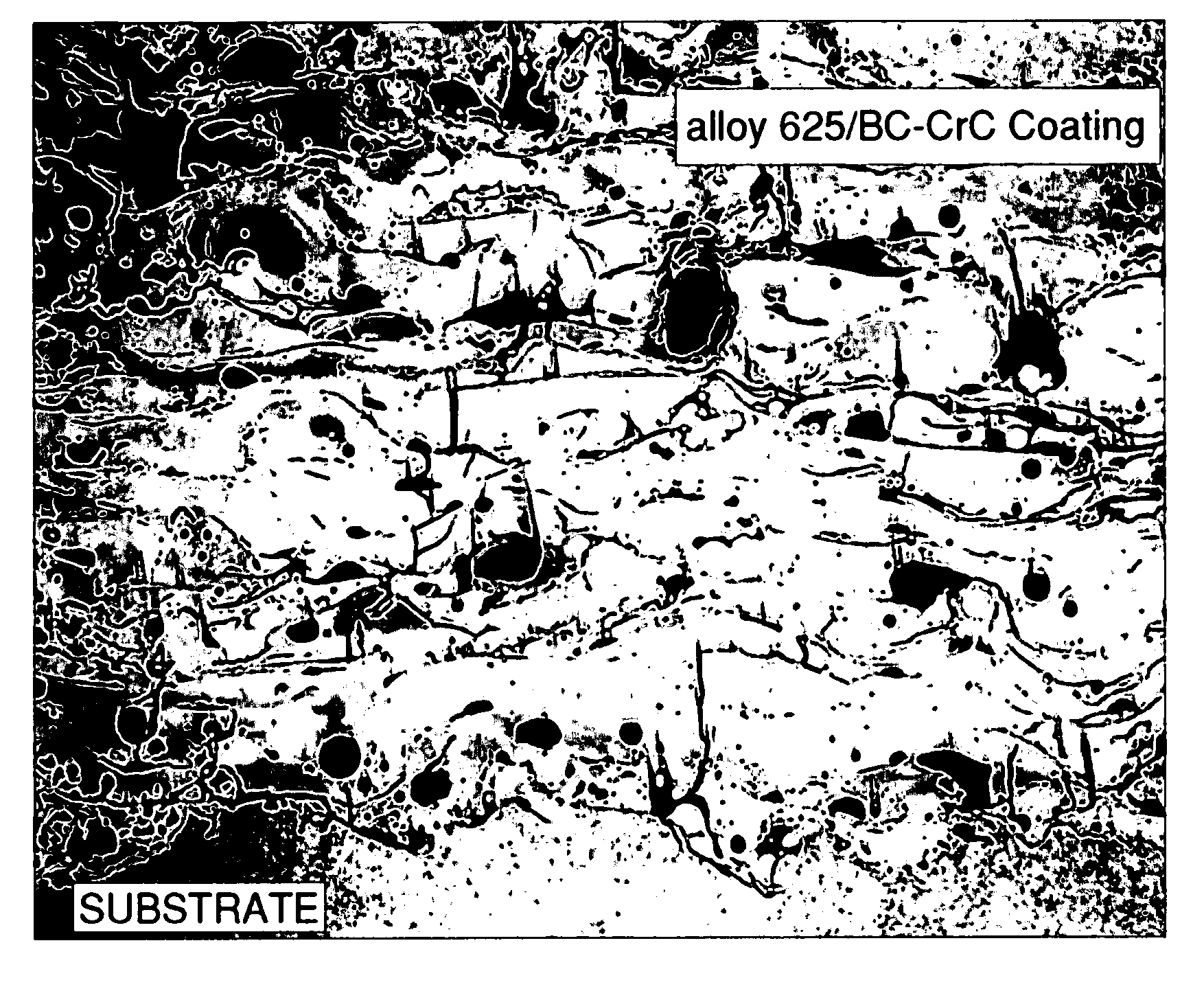
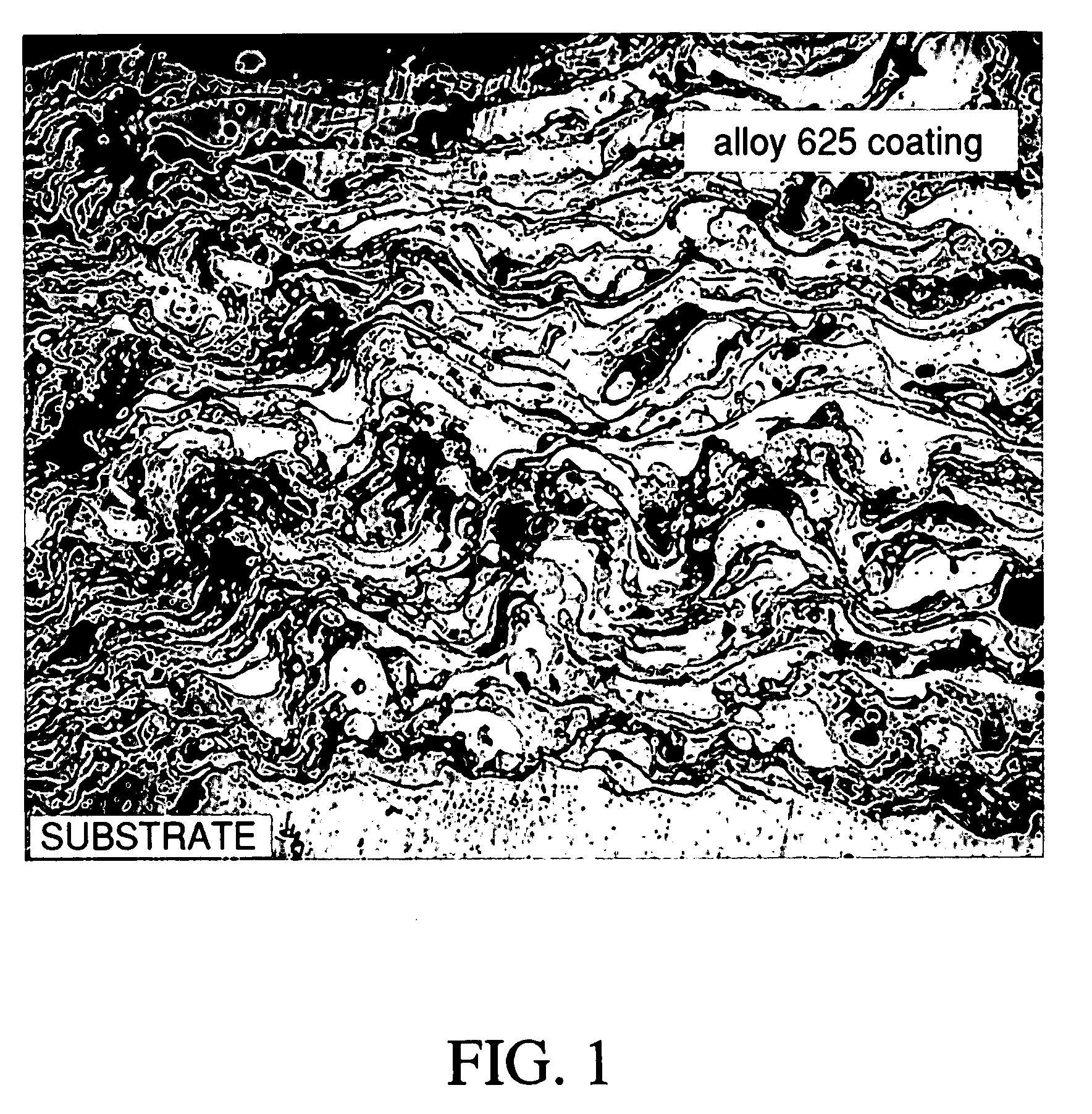
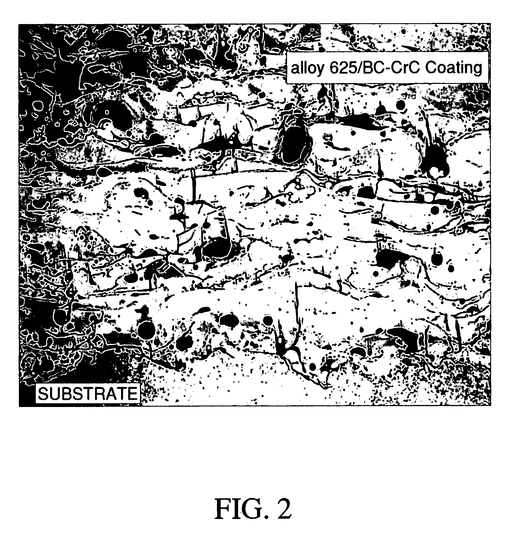
[0033]As stated above, in addition to good toughness, wear resistance, increased metal binder hardness, and improved bonding of the coating to the substrate, the inner core formulation of the present invention also inhibits oxide formation. This characteristic of the boron carbide / chrome carbide formulation is illustrated in FIGS. 1 and 2.

[0034]FIG. ...


PUM

PropertyMeasurementUnit
diameteraaaaaaaaaa
wear resistantaaaaaaaaaa
corrosion resistantaaaaaaaaaa

Abstract

A composite wire for producing a wear resistant and corrosion resistant coating on a substrate by thermal spraying, spray and fuse, or welding techniques are disclosed. The physical properties of the coating are particularly suited for high-temperature erosion-corrosion environments. The resultant coating exhibits good hardness, toughness, and bonding characteristics. The composite wire comprises a metallic outer sheath and an inner core containing boron carbide and chrome carbide.

Description

CROSS REFERENCES TO RELATED APPLICATIONS[0001]This application is a divisional of U.S. Nonprovisional application Ser. No. 10 / 854,826 filed May 27, 2004, now ______, which claims priority to U.S. Provisional Application No. 60 / 476,875 filed Jun. 6, 2003.STATEMENT REGARDING FEDERALLY SPONSORED RESEARCH OR DEVELOPMENT[0002]Not Applicable.FIELD OF THE INVENTION[0003]The present invention relates to coatings for substrates, particularly metallic substrates. More specifically, the invention relates to composite wires or cored wires for forming wear-resistant and corrosion-resistant coatings on metallic substrates by thermal spraying processes, spray and fuse processes, or by welding techniques. The invention also relates to methods of employing the composite or cored wires to apply wear-resistant and corrosion-resistant coatings to substrates.BACKGROUND OF THE INVENTION[0004]Thermal spraying, i.e. the generic name for a class of processes that allow the depositing molten or semi-molten m...

Claims


Application Information

Patent Timeline
Patent Type & Authority Applications(United States)
IPC IPC(8): C23C4/10C23C4/12B23K35/02B23K35/32C23C4/06
CPCB23K35/0266C23C4/125C23C4/06B23K35/327C23C4/131
Inventor SEITZ, MICHAEL
Owner INTEGRATED GLOBAL SERVICES
Learn More