
Continuous Method For Production Of A Regioselective Porous Hollow Fibre Membrane

a porous hollow fibre and continuous method technology, applied in the direction of membranes, separation processes, other chemical processes, etc., can solve the problems of undesired adhesion, solvents, and large amount of reaction chemicals

Active Publication Date: 2007-12-27
GAMBRO LUNDIA AB +1
View PDF9 Cites 17 Cited by
  • Summary
  • Abstract
  • Description
  • Claims
  • Application Information

AI Technical Summary

Benefits of technology

[0073] A major advantage of the present invention compared to prior art is that porous hollow fibre membrane substrates may be functionalised in a more homogeneous way on the desired surface areas of the membrane. Further, said functionalisation may take place in a continuous way implying a more economic process, consuming a smaller amount of precursor gas, compared to discontinuous processes.
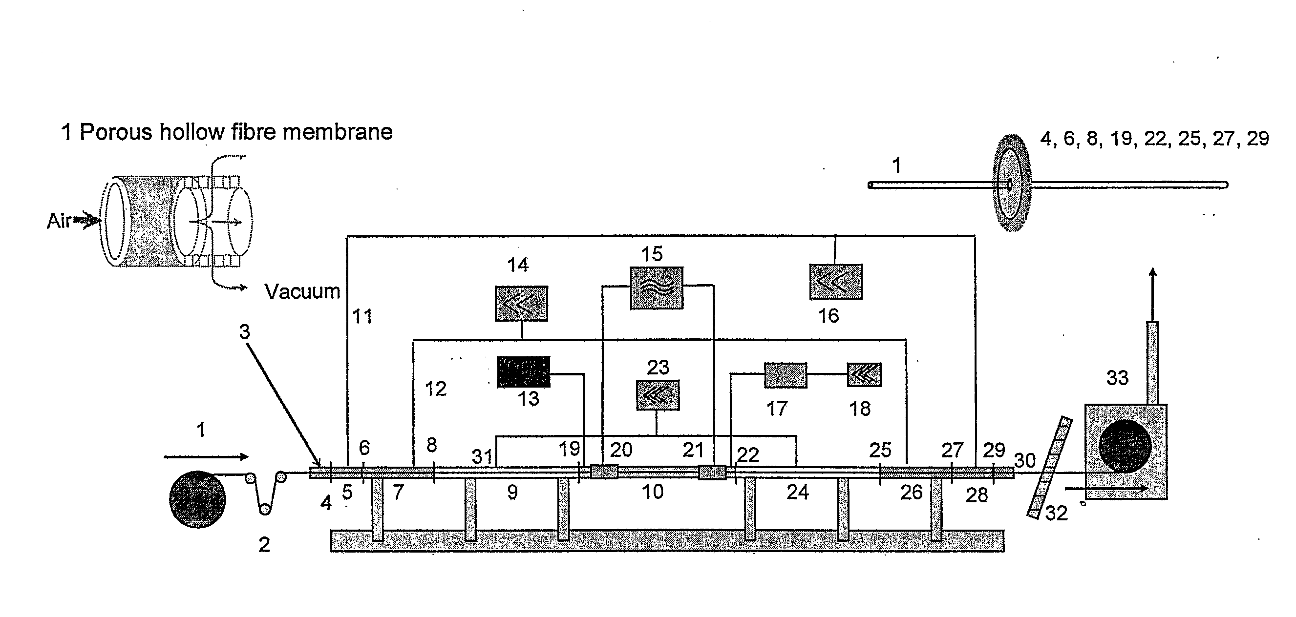
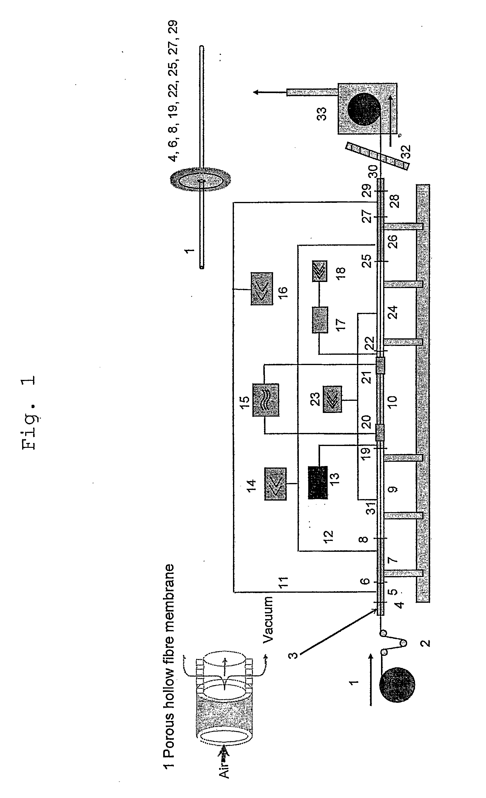
[0074] The functional groups to be introduced on the membrane substrate surfaces of interest are preferably amino groups originating from such molecules as amino compounds (diamines, triamines), e.g. diaminocyclohexane (DACH) and diethylenetriamine (DETA), but also from all organic precursors with primary amino groups or mixtures of hydrogen with nitrogen or ammonia, provided their vapour pressure is high enough to give a substantial amount of the molecule containing the functional groups in the vapour phase. Further, other functional groups than amino groups can be introduced, e.g. carboxyl, hydroxyl, sulphonic acid, ester or epoxy groups, when precursors comprising corresponding functions are used instead of compounds containing amino functions.
[0075] Optionally, a stabilising carrier gas, which is chemically inert during the gas plasma reaction, may be mixed with the precursor gas before or in connection with the addition thereof into the plasma ignition chamber 10. Examples of the carrier gas are helium, nitrogen, hydrogen, and argon, or mixtures thereof.
[0076] The microporous hollow fibre membranes produced according to the present invention are made of a biocompatible polymeric material, e.g. polyethersulfone (PES), polyvinylpyrrolidone (PVP), polypropylene (PP), polysulfone (PSU), polymethylmethacrylate (PMMA), polycarbonate (PC), polyacrylonitrile (PAN), polyamide (PA), polytetrafluorethylene (PTFE), cellulose acetate (CA), cellulose nitrate or regenerated cellulose. The length of the porous hollow membrane substrate 1 is not restricted upwards and it may be continuously fed into the vacuum system in the apparatus according to the present invention directly from its production line. In the examples below, the length of the membrane substrate is 1000 m, but it may be smaller or greater.
[0077] The inner diameter of the hollow fibres is normally 70-700 μm, e.g. 200-400 μm; the wall thickness is normally 20-150 μm, e.g. 50-100 μm; the pore diameter is 0.05-5.0 μm, e.g. 0.2 μm, the outer diameter is 110-1000 μm, e.g. 300-800 μm, such as 420 μm; the porosity is 50-90%, e.g. 65%; and the tortuosity is 1-3; e.g. 1.5. After functionalisation the fibres are normally arranged in modules e.g. containing a bundle of 10 up to more than 10 000 fibres. Experimental modules contain 10-100 fibres. Final modules for blood treatment contain more than 1000 fibres.
[0078] According to the present invention the hollow fibres used for the microporous hollow fibre membrane in one embodiment are made of a mixture of polyethersulfone and polyvinylpyrrolidone with an inner diameter of 320 μm, a wall thickness of 50 μm and a pore diameter of 0.2 μm.

Problems solved by technology

Such an adhesion is undesired.
This undesired activation of blood constituents in such membranes has since long been a great problem, in particular the accompanying undesired elimination of thrombocytes from the blood.
Several attempts have been made to solve this problem to prepare microporous hollow fibre membranes lacking the above-mentioned ligands or activated sites on the blood side of the membrane, but so far only complicated processes requiring large amounts of reaction chemicals and solvents have been found.
Moreover, these processes are also expensive, ineffective and not environmentally friendly, thereby creating problems highly needed to solve.
In many cases the corresponding physico-chemical surface compositions are not suitable for appropriate system integration, or these do not fit to the desired interaction with a contacting solid, liquid or gaseous counterpart.
But this advantage is basically accompanied by lower quality in the resulting surface finish.
None of these patents excludes porous materials as substrates which, due to their low mechanical strength, high void volume and inner surface area, may lead to the problem of an intense transport of air into the vacuum system.
The problem arises when there is a significant flow resistance of the porous structure to exhaust the air out of the lumen.
Additionally, this distance gradient of the local lumen pressure cannot be determined in a straightforward manner.

Method used


Image

  • Continuous Method For Production Of A Regioselective Porous Hollow Fibre Membrane
  • Continuous Method For Production Of A Regioselective Porous Hollow Fibre Membrane
  • Continuous Method For Production Of A Regioselective Porous Hollow Fibre Membrane

Examples


example 1

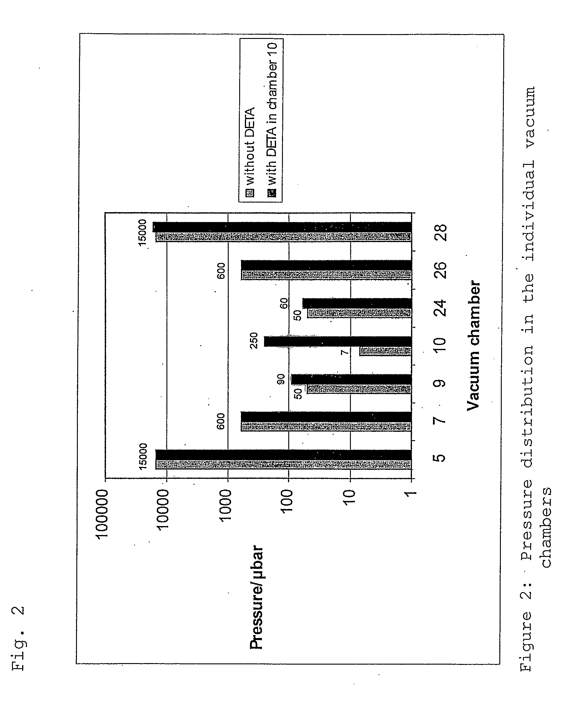
[0104] 1000 m of a porous polyarylethersulfone-polyvinyl-pyrrolidone (PAES / PVP) hollow fibre membrane substrate 1 with an outer shell diameter of 333 μm and a wall thickness of 38 μm were fed through the vacuum sealed plasma ignition chamber 10 (length: 67 cm, diameter: 2.5 cm) with a velocity of 23.5 m / min. Into said chamber 10 a precursor gas consisting of diethylenetriamine (DETA) with a pressure of 0.25 mbar was introduced with a view to depositing an amine containing carbohydrate thin film on the porous surface of the membrane. The plasma was excited with a 13.56 MHz pulsed RF power of 35 W (1 ms on, 5 ms off time). After this plasma treatment the density of amino groups was measured using the Sulfo-SDTB test (Pierce Inc. prod. No. 28610). A value of 1.7 μmol / g membrane was found. Additionally, the surface bound amino groups were derivatised with ligands using 5% pentafluorobenzaldehyde (PFBA) in cyclohexane with a contact time of 2 hrs and Soxhlet extraction with cyclohexane o...

example 2

[0105] Another sample of a PAES / PVP hollow fibre membrane substrate 1 with a shell diameter of 325 μm and a wall thickness of 39 μm was fed through the vacuum sealed plasma ignition chamber 10. As precursor gas again DETA with a pressure of 0.25 mbar was fed into said chamber 10. The hollow fibre transfer velocity was 6.3 m / min and a pulsed RF power 10 W (1 ms on, 5 ms off time) was used. The Sulfo-SDTB test indicated an amino group density of 1.7 μmol / g membrane. After the amino functionalisation the fibers were modified by graft polymerisation with dimethylaminopropylacrylamide according to EP03020986.0. For further SEM investigations samples of the modified hollow fibre membranes were cut in contact with frozen deionised water or under liquid nitrogen into half pipes and cross sections. These samples were brought into contact over night with positively or negatively charged 20 nm gold nanobeads. The charging is realized using the layer by layer technique of polyelectrolyte adsorp...


PUM

PropertyMeasurementUnit
Pressureaaaaaaaaaa
Pressureaaaaaaaaaa
Affinityaaaaaaaaaa

Abstract

A continuous method for production of a porous hollow fibre membrane having regioselective affinity for compounds in blood or other biologically active fluids to be removed during purification of blood or said fluids is disclosed, as well as a porous hollow fibre membrane produced by said method, an adsorption device containing such a porous hollow fibre membrane, and use of such a porous hollow fibre membrane.

Description

TECHNICAL FIELD OF THE INVENTION [0001] The present invention relates to a continuous method for production of a porous hollow fibre membrane having regioselective affinity for compounds in blood or other biologically active fluids to be removed during purification of blood or said fluids, a porous hollow fibre membrane produced by said method, an adsorption device containing such a porous hollow fibre membrane, and use of such a porous hollow fibre membrane. BACKGROUND ART [0002] Porous hollow fibre membranes are examples of porous affinity membranes having a blood side and a filtrate side. Such membranes are well known for analytical, diagnostic or therapeutical purposes. For example, such porous hollow fibre membranes are useful for the treatment of blood or other biologically active fluids with a view to eliminating undesired compounds therefrom, i.e. in therapeutic apheresis. Porous hollow fibre membranes are normally composed of a bundle of separate microporous hollow fibres. ...

Claims


Application Information

Patent Timeline
IPC IPC(8): B01D69/08B01D67/00B01DB01D61/00B01D69/02B01D71/68B01J20/28B01J20/32
CPCB01D61/00B01D2323/38B01D69/02B01D69/08B01D71/68B01J20/28004B01J20/28021B01J20/28023B01J20/28033B01J20/28069B01J20/28085B01J20/261B01J20/262B01J20/265B01J20/3085B01J20/321B01J20/3212B01J20/3217B01J20/3219B01J20/3248B01J20/3253B01J20/3274B01J2220/445B01D67/0093B01D67/00931
Inventor KRAUSE, BERNDGOHL, HERMANNBECK, CHRISTOPHDANNENMAIER, JURGENMULLER, MICHAELKURZ, EDMUNDMALTHANER, HEINRICHOEHR, CHRISTIANSTORR, MARKUS
Owner GAMBRO LUNDIA AB
Learn More