
Membrane electrode assembly for use in solid polymer electrolyte fuel cell

a solid polymer electrolyte and fuel cell technology, applied in the direction of fuel cell details, cell components, electrochemical generators, etc., can solve the problems of insufficient depletion of resources, and inability to achieve sufficient etc., to ensure gas diffusivity, excellent electric power generation performance, and the ability to discharge the generated water

Active Publication Date: 2007-09-20
HONDA MOTOR CO LTD
View PDF1 Cites 8 Cited by
  • Summary
  • Abstract
  • Description
  • Claims
  • Application Information

AI Technical Summary

Benefits of technology

[0014]An object of the present invention is to provide a membrane electrode assembly for use in a solid polymer electrolyte fuel cell which assembly can ensure the gas diffusivity, the capability of discharging the generated water and the moisture retentivity, and can attain an excellent electric power generation performance in the gas atmosphere under a wide variety of humidity conditions, through overcoming the above described problems.
[0016]In the membrane electrode assembly for use in a solid polymer electrolyte fuel cell, when hydrogen is supplied to the anode side and air is supplied to the cathode side, the oxygen concentration in the air as the cathode gas is 20% and is lower than the concentration of the anode gas, and hence the improvement of the cathode gas diffusivity leads to the improvement of the electric power generation performance.
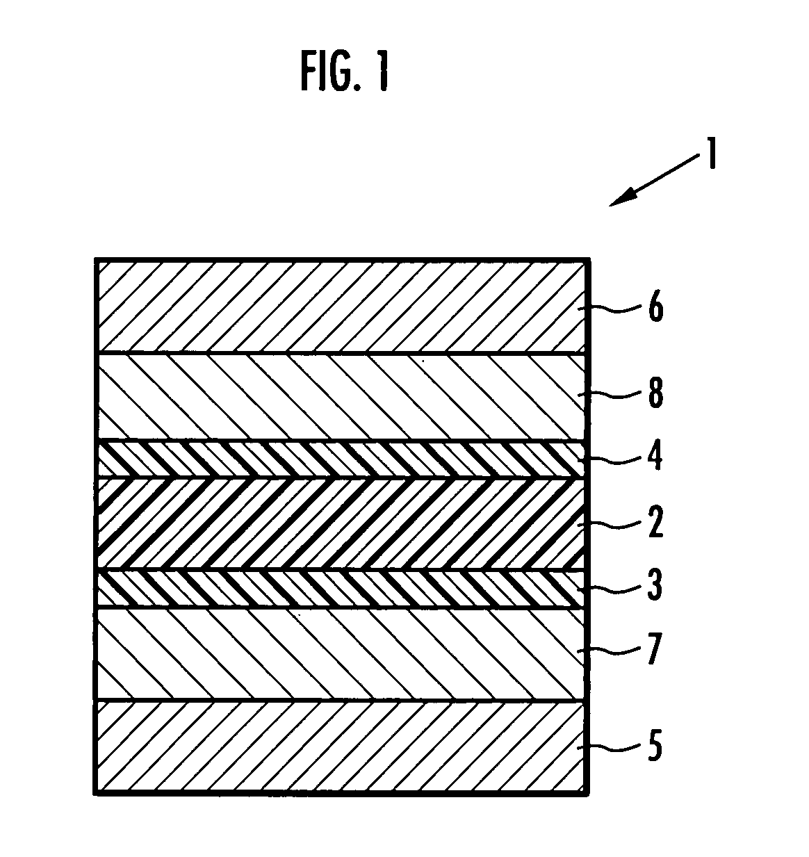
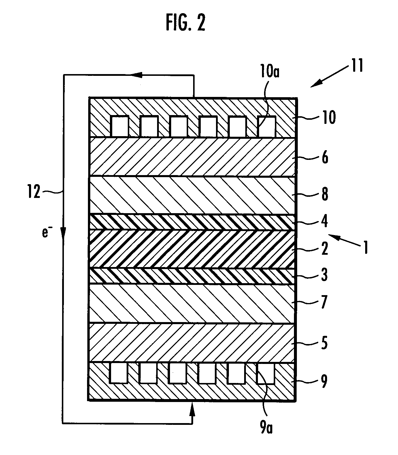
[0017]Accordingly, the membrane electrode assembly for use in a solid polymer electrolyte fuel cell of the present invention comprises two intermediate layers comprising pores and disposed respectively between one of the electrode catalyst layers and the gas diffusion layer pairing therewith and between the other of the electrode catalyst layers and the gas diffusion layer paring therewith, and the volume per unit area and per unit mass of the pores falling within a pore size range from 0.1 to 10 μm in the intermediate layer in the cathode side is made larger than the volume per unit area and per unit mass of the pores falling within a pore size range from 0.1 to 10 μm in the intermediate layer in the anode side. The pores in the intermediate layers can favorably carry out, through having the pore sizes falling within the range from 0.1 to 10 μm, the gas diffusion and the discharge of the generated water.
[0018]Consequently, the membrane electrode assembly for use in a solid polymer electrolyte fuel cell of the present invention can ensure sufficient gas diffusivity and sufficient capability of discharging the generated water in the cathode side, and can ensure sufficient moisture retentivity in the anode side. Consequently, the membrane electrode assembly for use in a solid polymer electrolyte fuel cell of the present invention can attain an excellent electric power generation performance in the gas atmosphere under a wide variety of humidity conditions.
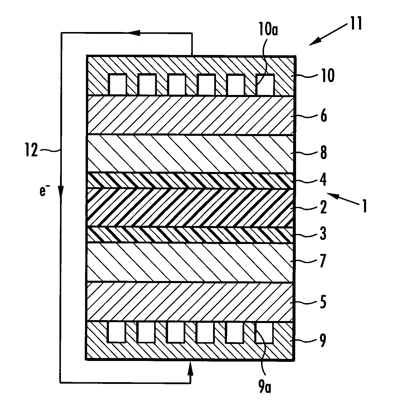
[0019]In the present invention, it is preferable that the volume per unit area and per unit mass of the pores falling within the specified pore size range in the intermediate layer in the cathode side falls within a range from 1.7 to 4.3 μl / cm2 / mg, and the volume per unit area and per unit mass of the pores falling within the specified pore size range in the intermediate layer in the anode side falls within a range from 0.5 to 1.4 μl / cm2 / mg. On the basis of the conditions such that the volume of the pores per unit area and per unit mass in each of the intermediate layer in the cathode side and the intermediate layer in the anode side falls within the above described range, the moisture content in the solid polymer electrolyte membrane is ensured under low-humidity conditions such as high load operation conditions, and there can be ensured the diffusivity of the cathode gas tending to affect the electric power generation performance under the low-temperature and high-humidity conditions as can be encountered at the time of start-up. Consequently, the membrane electrode assembly for use in a solid polymer electrolyte fuel cell of the present invention can attain a satisfactory electric power generation performance both under the high-humidity conditions and under the low-humidity conditions of the reductive gas or the oxidative gas.

Problems solved by technology

Oil resources have been depleted, and at the same time, environmental problems including the global warming caused by fossil fuel consumption have been increasingly serious.
However, there is a problem in that no sufficient electric power generation performance can be attained when the humidity of the reductive gas or the oxidative gas is low.
Consequently, a long-time operation of the fuel cell makes excessive the moisture in the membrane electrode assembly to inhibit the diffusion of the reductive gas or the oxidative gas, and hence this case also suffers from a problem that no sufficient electric power generation performance can be attained.
However, any of the above described conventional techniques involves disadvantages such that the pore size made smaller leads to insufficient gas diffusivity and insufficient capability of discharging the generated water, and the pore size made larger leads to insufficient water retentivity.

Method used


Image

  • Membrane electrode assembly for use in solid polymer electrolyte fuel cell
  • Membrane electrode assembly for use in solid polymer electrolyte fuel cell
  • Membrane electrode assembly for use in solid polymer electrolyte fuel cell

Examples


example 1

[0041]In the present example, at the beginning, the gas diffusion layers 5 and 6 were formed by impregnating a sheet of carbon paper with a 10% by weight solution of tetrafluoroethylene-tetrafluoropropylene copolymer and by thereafter heat treating the impregnated carbon paper at 380° C. for 30 minutes for water-repellent treatment.

[0042]Next, a mixed paste for the cathode intermediate layer was prepared by mixing, under stirring with a three-dimensional stirrer at 1300 rpm for 10 minutes, 10 g of a vapor grown carbon (trademark: VGCF, manufactured by Showa Denko Co., Ltd.) as an electrically conducting agent having pore formability, 10 g of a polytetrafluoroethylene powder (trade name: Fluon L170J, manufactured by Asahi Glass Co., Ltd.) as a water-repellent resin and 220 g of ethylene glycol as a solvent. Then, the mixed paste for the cathode intermediate layer was applied onto the gas diffusion layer 5 in the cathode side by means of screen printing, and thereafter heat treated at...

example 2

[0053]In the present example, a membrane electrode assembly 1 shown in FIG. 1 was fabricated in the same manner as in Example 1 except that a mixture prepared by mixing 7.0 g of a vapor-grown carbon (trademark: VGCF, manufactured by Showa Denko Co., Ltd.) and 3.0 g of a carbon powder (trade name: Vulcan XC-72, manufactured by Cabot Corp.) was used as an electrically conducting agent having pore formability in place of the electrically conducting agent having pore formability used to prepare the mixed paste for the cathode in Example 1.

[0054]The coating amounts (masses) per unit area and the pore volumes of the intermediate layers 7 and 8 were measured in the same manner as in Example 1. The results thus obtained are shown in Table 1.

[0055]The electric power generation performances under high humidity and low humidity of the membrane electrode assembly 1 were evaluated in the same manner as in Example 1. The results thus obtained are shown in Table 2 and FIG. 3.

example 3

[0056]In the present example, a membrane electrode assembly 1 shown in FIG. 1 was fabricated in the same manner as in Example 1 except that a mixture prepared by mixing 10.0 g of a vapor-grown carbon (trademark: VGCF, manufactured by Showa Denko Co., Ltd.) and 1.0 g of a polymethylmethacrylate bead of 5 μm in particle size (trade name: Techpolymer MBX-5, manufactured by Sekisui Plastics Co., Ltd.) as a pore-forming agent was used as an electrically conducting agent having pore formability in place of the electrically conducting agent having pore formability used to prepare the mixed paste for the cathode in Example 1.

[0057]The coating amounts (masses) per unit area and the pore volumes of the intermediate layers 7 and 8 were measured in the same manner as in Example 1. The results thus obtained are shown in Table 1.

[0058]The electric power generation performances under high humidity and low humidity of the membrane electrode assembly 1 were evaluated in the same manner as in Example...


PUM

PropertyMeasurementUnit
pore sizeaaaaaaaaaa
pore sizeaaaaaaaaaa
porosityaaaaaaaaaa

Abstract

The present invention provides a membrane electrode assembly for use in a solid polymer electrolyte fuel cell which assembly can ensure the gas diffusivity, the capability of discharging the generated water and the moisture retentivity, and can attain an excellent electric power generation performance in the gas atmosphere under a wide variety of humidity conditions. The membrane electrode assembly comprises: a cathode electrode catalyst layer 3 and an anode electrode catalyst layer 4 respectively disposed on one side and the other side of a solid polymer electrolyte membrane 2; gas diffusion layers 5 and 6 disposed respectively on the sides of the electrode catalyst layers 3 and 4; and intermediate layers 7 and 8 comprising pores and disposed respectively between the electrode catalyst layer 3 and the gas diffusion layer 5 and between the electrode catalyst layer 4 and the gas diffusion layer 6. The volume per unit area and per unit mass (pore volume) of the pores having pore size of 0.1 to 10 μm in the intermediate layer 7 in the cathode side is larger than that in the intermediate layer 8 in the anode side. The pore volume of the intermediate layer 7 in the cathode side is 1.7 to 4.3 μl / cm2 / mg and that of the intermediate layer 8 in the anode side is 0.5 to 1.4 μl / cm2 / mg. The intermediate layers 7 and 8 are each formed of a water-repellent resin comprising an electrically conducting particle.

Description

BACKGROUND OF THE INVENTION[0001]1. Field of the Invention[0002]The present invention relates to a membrane electrode assembly for use in a solid polymer electrolyte fuel cell.[0003]2. Description of the Related Art[0004]Oil resources have been depleted, and at the same time, environmental problems including the global warming caused by fossil fuel consumption have been increasingly serious. Accordingly, fuel cells have attracted attention as clean electric power supplies for electric motors not involving the generation of carbon dioxide, and thus have been extensively developed and partially begin to be used practically. When the fuel cells are mounted in automobiles and the like, solid polymer electrolyte fuel cells using solid polymer electrolyte membranes are preferably used because such fuel cells can easily provide high voltage and large electric current.[0005]Known as a membrane electrode assembly to be used in the solid polymer electrolyte fuel cell is a membrane electrode a...

Claims


Application Information

Patent Timeline
Patent Type & Authority Applications(United States)
IPC IPC(8): H01M4/94H01M4/86H01M8/02H01M8/10
CPCH01M4/8807H01M8/0243Y02E60/521H01M8/1004H01M8/0245Y02E60/50
Inventor TANAKA, SHINTAROASANO, YOICHITAKAHASHI, RYOICHIROYAMAWAKI, TAKUMA
Owner HONDA MOTOR CO LTD
Learn More