
Laser processing method

a laser processing and laser technology, applied in the field of laser processing methods, can solve problems such as cutting error, and achieve the effect of reducing the number of manufacturing steps and high precision

Active Publication Date: 2007-07-12
HAMAMATSU PHOTONICS KK
View PDF111 Cites 158 Cited by
  • Summary
  • Abstract
  • Description
  • Claims
  • Application Information

AI Technical Summary

Benefits of technology

[0007] In view of such circumstances, it is an object of the present invention to provide a laser cutting method which overcomes problems such as those mentioned above, and can cut an object to be processed with a high precision even when the object to be processed has various laminate structures.
[0010] By attaching a protective film to the front face of an object to be processed, these laser processing methods allow the object to be mounted on a table such that the rear face faces up, whereby the inside of the (semiconductor) substrate can favorably be irradiated with laser light from the rear face of the object. The modified region (molten processed region) formed by a phenomenon known as multiphoton absorption can form a cutting start region within the substrate along a desirable line to cut along which the object should be cut, whereby the object can be cut from the cutting start region acting as a start point. Attaching an expandable film to the rear face of the object and expanding the film can easily separate a plurality of cut parts of the object from each other. Namely, these laser processing method can form a cutting start region without directly irradiating the laminate part on the front face of the object with laser light, and cut the substrate by breaking it with a high precision while using a relatively small force from the cutting start region acting as a start point, thereby easily separating cut pieces of the object from each other. Therefore, even when the object to be processed has various laminate structures, these laser processing methods can cut the object with a high precision.
[0014] Even when the object to be processed has various laminate structures, these laser processing methods can cut the object with a high precision because of the same reason as with the laser processing methods mentioned earlier. Also, by applying an external force to the object when cutting the object into a plurality of parts, these methods can easily cut the object from the cutting start region acting as a start point.
[0017] Even when the object to be processed has various laminate structures, these laser processing methods can cut the object with a high precision because of the same reason as with the laser processing methods mentioned earlier. Also, by expanding the expandable film, these methods can apply a tensile stress to the cutting start region of the object, thereby performing the step of cutting the object and the step of separating a plurality of parts from each other at the same time, thus reducing the number of manufacturing steps.
[0018] Preferably, in the above-mentioned laser processing methods in accordance with the present invention, the rear face of the object is shaved so as to thin the substrate of the object before forming the cutting start region in the object. This can accurately cut the object from the cutting start region acting as a start point with a smaller force or without requiring any special force.
[0019] Preferably, in the above-mentioned laser processing methods in accordance with the present invention, the protective film is removed after the expandable film is attached to the object. This can hold the object formed with the cutting start region without breaking it up. Alternatively, it will be preferred if the protective film is removed after a plurality of parts of the object are separated from each other by expanding the expandable film. This can protect a plurality of parts until the plurality of parts are taken out after the object is cut.

Problems solved by technology

However, sawdust or lubricant / washing water may enter a gap formed between a glass substrate and another glass substrate in the blade dicing method when the object is one for a liquid crystal display device mentioned above, for example.
In the diamond scribe method, on the other hand, a scribe line must be formed on not only the front face but also the rear face of the object when the object includes a substrate having a high hardness such as an Al2O3 substrate or when the object is one in which glass substrates are bonded together, whereby errors in cutting may occur because of a misalignment between the respective scribe lines formed on the front and rear faces.

Method used


Image

  • Laser processing method
  • Laser processing method
  • Laser processing method

Examples


first example

[0117]FIGS. 18 and 19 are flowcharts for explaining a first example of the laser processing method in accordance with the embodiment. FIGS. 20 to 22 are sectional views of the wafer 1a for explaining the laser processing method in accordance with this example.

[0118] Referring to FIG. 18, a protective tape 25 as a protective film for protecting a laminate 4 is initially attached to the front face 3 of the wafer 1a (S1, FIG. 20A). Various materials can be used as a material for the protective tape 25 as long as they have a cushioning effect for protecting the laminate part 4 and do not affect operating characteristics of the laminate part 4. Chosen as the material for the protective tape 25 in this embodiment is one which can absorb shocks while being removable when irradiated with UV rays.

[0119] Subsequently, a cutting start region 8 is formed within the substrate 15 of the wafer 1a along a line 5 along which the object is intended to be cut (S3, FIG. 20B). The wafer 1a shown in FI...

second example

[0139]FIG. 24 is a flowchart showing a second example of the laser processing method in accordance with this embodiment. FIGS. 25 to 27 are sectional views of the wafer 1a for explaining this example. This example differs from the above-mentioned first example in three points, i.e., (1) that the substrate is shaved so as to become thinner; (2) that no breaking with the knife edge 33 or the like is effected; and (3) that the protective tape 25 is peeled off after dividing the wafer 1a into a plurality of chip parts 24.

[0140] Referring to FIG. 24, the protective tape 25 is initially attached to the front face 3 of the wafer 1a (S21, FIG. 25A). This step is the same as the step S1 in the first example and thus will not be explained in detail.

[0141] Subsequently, the rear face 21 of the wafer 1a is shaved (S23, FIG. 25B). Here, the substrate 15 is shaved (ground) until it has a thickness of 30 μm to 50 μm, for example. In order for the laser light L to be favorably made incident on th...

third example

[0150]FIG. 28 is a flowchart showing a third example of the laser processing method in accordance with this embodiment. This example differs from the above-mentioned first example in one point, i.e., (1) that the breaking with the knife edge 33 or the like is not effected. This modified example will be explained with reference to FIGS. 20 to 22 which are shown in the first example.

[0151] Referring to FIG. 28, the protective tape 25 is initially attached to the front face 3 of the wafer 1a (S41, FIG. 20A). Subsequently, the cutting start region 8 is formed within the substrate 15 of the wafer 1a along the line 5 along which the object is intended to be cut (S43, FIG. 20B). Then, the expandable tape 23 is attached to the rear face 21 of the wafer 1a (S45, FIG. 20C). These steps are the same as the steps S1 to S5 in the above-mentioned first example, respectively, and thus will not be explained in detail.

[0152] Next, the protective tape 25 is irradiated with UV rays (S47, FIG. 21B), ...


PUM

PropertyMeasurementUnit
outer diameteraaaaaaaaaa
thicknessaaaaaaaaaa
sizeaaaaaaaaaa

Abstract

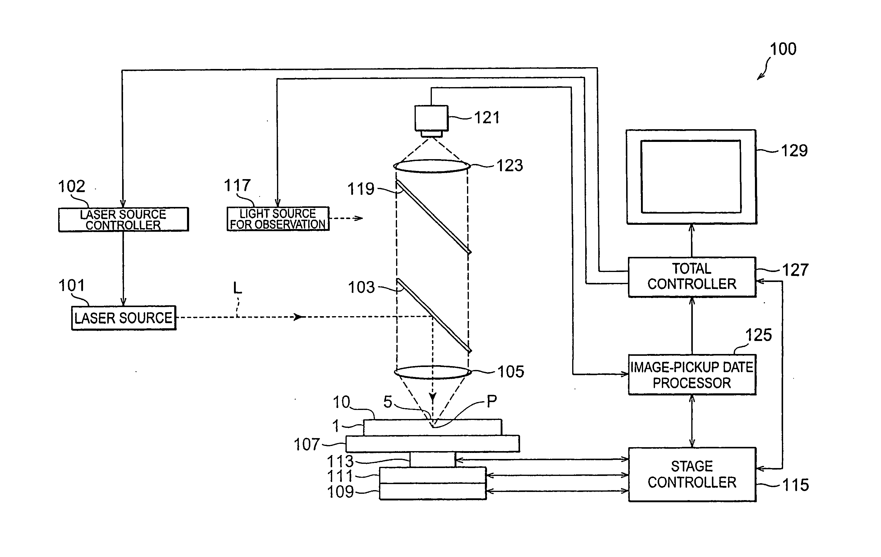
The present invention provides a laser processing method comprising the steps of attaching a protective tape 25 to a front face 3 of a wafer 1a, irradiating a substrate 15 with laser light L while employing a rear face of the wafer 1a as a laser light entrance surface and locating a light-converging point P within the substrate 15 so as to form a molten processed region 13 due to multiphoton absorption, causing the molten processed region 13 to form a cutting start region 8 inside by a predetermined distance from the laser light entrance surface along a line 5 along which the object is intended to be cut in the wafer 1a, attaching an expandable tape 23 to the rear face 21 of the wafer 1a, and expanding the expandable tape 23 so as to separate a plurality of chip parts 24 produced upon cutting the wafer 1a from the cutting start region 8 acting as a start point from each other.

Description

TECHNICAL FIELD [0001] The present invention relates to a processing method and, in particular, to a processing method using a laser. BACKGROUND ART [0002] Techniques for highly accurately cutting objects to be processed having various laminate structures such as those in which semiconductor active layers such as GaN are grown as crystals on an Al2O3 substrate for semiconductor devices and those in which glass substrates are bonded to other glass substrates for liquid crystal display devices have recently been in demand. [0003] For cutting the objects to be processed having these laminate structures, it has conventionally been common to use a blade dicing or diamond scribe method. [0004] The blade dicing method is a method in which an object to be processed is cut by being shaved with a diamond blade or the like. On the other hand, the diamond scribe method is a method in which a diamond point tool forms a scribe line on the front face of an object to be processed, and a knife edge ...

Claims


Application Information

Patent Timeline
Patent Type & Authority Applications(United States)
IPC IPC(8): B23K26/00B23K26/38B28D1/22B28D5/00
CPCB28D1/221B28D5/0011B28D5/0052Y10S148/903B23K26/4075B23K2201/40B23K26/0057B23K26/40B23K2103/50Y10T29/49254Y10T29/53465B23K26/53B23K2101/40B23K26/38B23K26/36
Inventor FUKUMITSU, KENSHIFUKUYO, FUMITSUGUUCHIYAMA, NAOKI
Owner HAMAMATSU PHOTONICS KK
Learn More