
Amine based compound and organic electroluminescence device using the same

a technology of organic electroluminescence and compound, which is applied in the direction of discharge tube luminescnet screen, discharge tube/lamp details, organic chemistry, etc., can solve the problems of elution, insufficient light emission lifetime of each film, and non-uniform film, etc., and achieves low ionization potential, high injection efficiency, and large band gap energy

Inactive Publication Date: 2007-06-14
IDEMITSU KOSAN CO LTD
View PDF0 Cites 7 Cited by
  • Summary
  • Abstract
  • Description
  • Claims
  • Application Information

AI Technical Summary

Benefits of technology

[0023] The amine-based compound of the present invention is useful as a hole injecting material or hole transporting material for an organic EL device or for an electrophotographic photosensitive member. An organic EL device using the amine-based compound of the present invention brings physical properties, that is, a low ionization potential, large band gap energy, high injection efficiency, and a high mobility into balance in an excellent manner, has high heat resistance, and shows high current efficiency and a long lifetime while maintaining good luminance / voltage characteristics and good current density / voltage characteristics.

Problems solved by technology

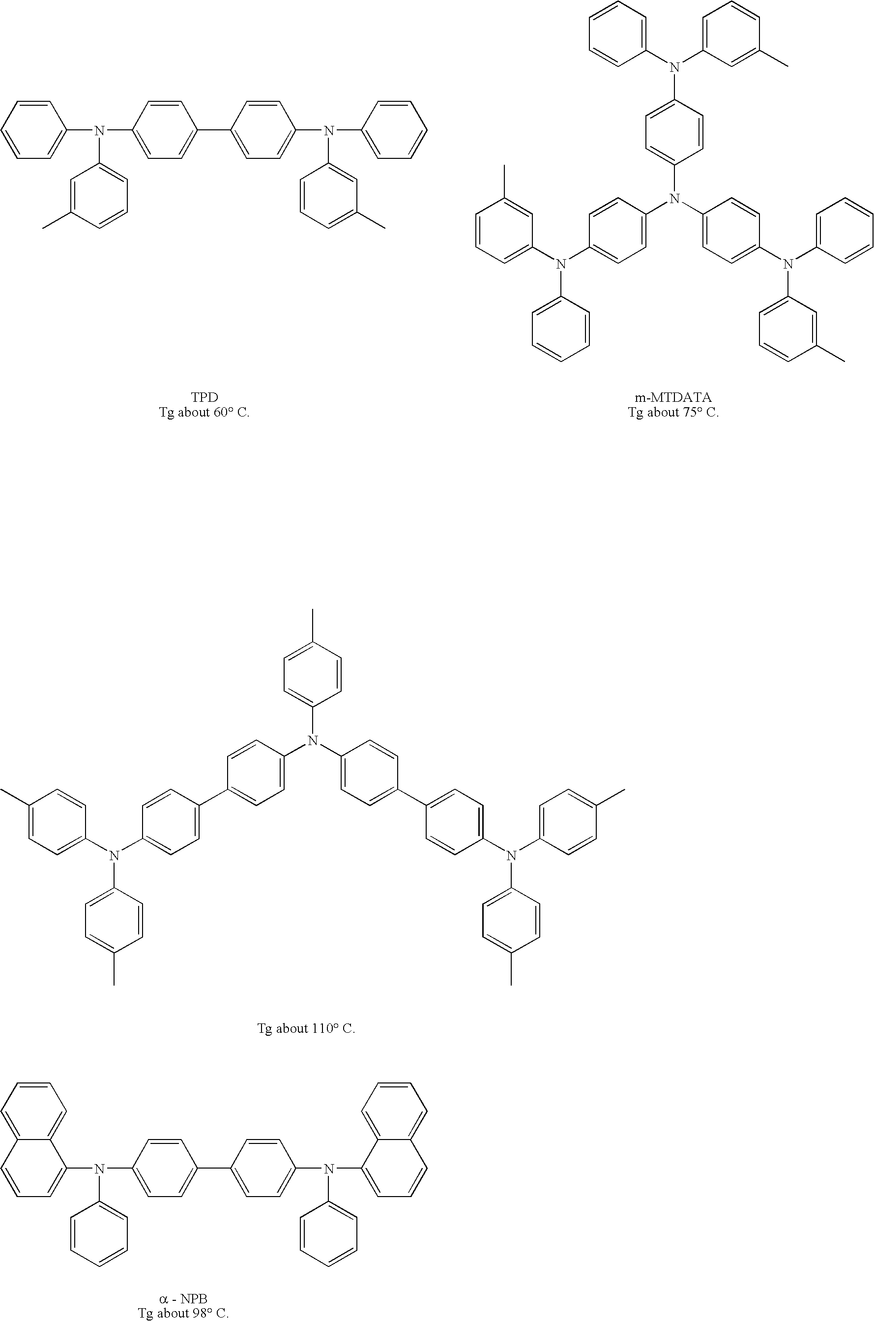
However, the following exemplified compounds each involve, for example, the problem in that each of the compounds has low heat resistance (glass transition temperature, Tg), and crystallizes after a lapse of a long time period even under a room temperature condition so that a film becomes non-uniform.
However, the device involves a problem of elution due to a solvent upon application of a hole injecting layer, a hole transporting layer, and a light emitting layer forming a laminate structure.
However, the light emission lifetime of each of them is not always sufficient, and an improvement in the light emission lifetime has been demanded.
However, the material has a low glass transition temperature and insufficient heat resistance.

Method used


Image

  • Amine based compound and organic electroluminescence device using the same
  • Amine based compound and organic electroluminescence device using the same
  • Amine based compound and organic electroluminescence device using the same

Examples


synthesis example 1 (

Synthesis of Compound 1)

[0176] A synthetic route for Compound 1 is shown below.

(1) Synthesis of Intermediate 1-1

[0177] 18.1 g (133 mmol) of benzothiadiazole were loaded into a 200-ml three-necked flask, and were dissolved in 42.9 ml of a 47% aqueous solution of HBr. 20 ml of bromine were dropped to the solution at room temperature over 20 minutes. Further, 13.3 ml of a 47% aqueous solution of HBr were added to the mixture, and the whole was refluxed for 24 hours. The temperature of the resultant was cooled to room temperature, and the resultant solid was dissolved in 700 ml of dichloromethane. After that, 400 ml of a saturated aqueous solution of sodium thiosulfate were added to the solution, and the whole was sufficiently extracted by using a separating funnel. Further, a dichloromethane layer was washed with 150 ml of distilled water 3 times, and was then dried with anhydrous sodium sulfate. Dichloromethane was concentrated to 200 ml, and the resultant was left at 4° C. for 24...

synthesis example 2 (

Synthesis of Compound 2)

[0187] A synthetic route for Compound 2 is shown below.

[0188] (1) Synthesis of Intermediate 2-1

[0189] 8.5 g of Intermediate 2-1 were obtained in a yield of 80% in the same manner as in the above item (3) of Synthesis Example 1 except that 4.4 g (FW 182, 24.3 mmol) of acenaphthenequinone were used instead of 5.1 g of 9,10-phenanthrenequinone.

[0190] (2) Synthesis of Compound 2

[0191] 3.0 g of an orange solid as Compound 2 were obtained in the same manner as in the above item (4) of Synthesis Example 1 except that Intermediate 2-1 (FW 438, 5.7 mmol, 2.3 g) was used instead of 2.5 g of Intermediate 1-3. The yield was 90%.

[0192] The results of measurement of the field desorption mass spectrum (FD-MS), ionization potential, and Tg (glass transition temperature) measured by differential scanning calorimetry (DSC) of the resultant product are shown below. [0193] FD-MS: Calcd. for C42H28N4=588Found=588 [0194] Ionization potential: 5.19 eV [0195] Tg: A peak temper...

example 1

[0208] A glass substrate with an ITO transparent electrode measuring 25 mm wide by 75 mm long by 1.1 mm thick (manufactured by GEOMATEC Co., Ltd.) was subjected to ultrasonic cleaning in isopropyl alcohol for 5 minutes. After that, the substrate was subjected to UV ozone cleaning for 30 minutes. The glass substrate with the transparent electrode line after the washing was mounted on a substrate holder of a vacuum deposition device. First, Compound 1 was formed into a film having a thickness of 60 nm on the surface on the side where the transparent electrode line was formed to cover the transparent electrode. The Compound 1 functions as a hole injecting layer. Next, an N,N,N′,N′-terakis(4-biphenyl)-4,4′-benzidine film (BPTPD film) having a thickness of 20 nm was formed on the Compound 1. The BPTPD film functions as a hole transporting layer. Further, Compound A having a thickness of 40 nm to be described below and doping Compound B at a deposition rate of 40:2 were simultaneously dep...


PUM

PropertyMeasurementUnit
ionization potentialaaaaaaaaaa
temperatureaaaaaaaaaa
boiling pointaaaaaaaaaa

Abstract

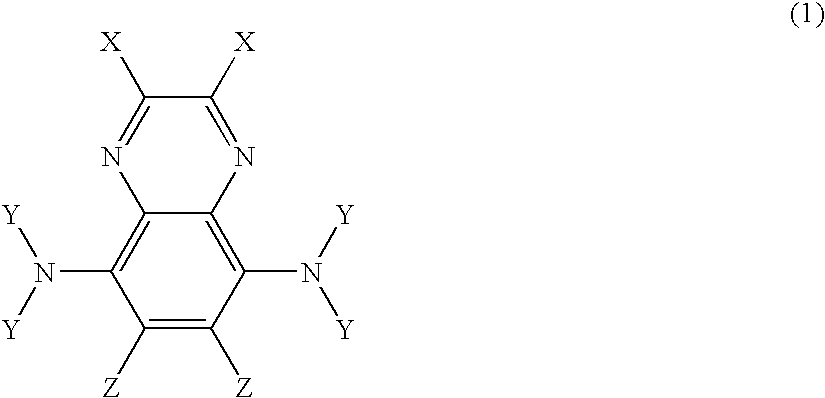
The present invention provides an organic electroluminescence device which: brings physical properties, that is, a low ionization potential, large band gap energy, high injection efficiency, and a high mobility into balance in an excellent manner; has high heat resistance; and shows high current efficiency and a long lifetime while maintaining good luminance / voltage characteristics and good current density / voltage characteristics, and a novel amine-based compound for realizing the device. The amine-based compound is of a specific structure containing a quinoxaline ring. The organic electroluminescence device includes an organic thin film layer composed of one or more layers including at least a light emitting layer, the organic thin film layer being interposed between a cathode and an anode. In the organic electroluminescence device, at least one layer of the organic thin film layer contains the amine-based compound alone or as a component of a mixture.

Description

TECHNICAL FIELD [0001] The present invention relates to an amine-based compound and an organic electroluminescence device using the compound, and more specifically, to an organic electroluminescence device having high heat resistance and showing high current efficiency and a long lifetime while maintaining good luminance / voltage characteristics and good current density / voltage characteristics, and an amine-based compound for realizing the device. BACKGROUND ART [0002] An organic electroluminescence (EL) device is a spontaneous light emitting device which utilizes the principle that a fluorescent substance emits light by energy of recombination of holes injected from an anode and electrons injected from a cathode when an electric field is applied thereto. The organic electroluminescence devices are not only highly visible because of the spontaneous light emission, but also excellent in impact strength because they are full solid devices, and thus the organic electroluminescence devic...

Claims


Application Information

Patent Timeline
Patent Type & Authority Applications(United States)
IPC IPC(8): H01J1/62C07D241/36H01J63/04
CPCC07D241/38C09K11/06C09K2211/1007C09K2211/1011C09K2211/1014H01L51/0058H01L51/0059H01L51/0072H01L51/0081H01L51/5012H01L51/5088H05B33/14H10K85/631H10K85/626H10K85/324H10K85/6572H10K50/17H10K50/11H10K85/615
Inventor INOUE, TETSUYAWATANABE, MASAMIKONDO, HIROFUMI
Owner IDEMITSU KOSAN CO LTD
Learn More