
Wavelength Converter, Lighting System, and Lighting System Assembly

a technology of wavelength converter and lighting system, which is applied in the direction of luminescent composition, semiconductor devices, chemistry apparatus and processes, etc., can solve the problems of poor color rendering property, failure to improve the luminous efficiency of the white light emitting unit, and less emission of green and blue fluorescent substances, so as to achieve high safety, color rendering property and luminous efficiency, and improve the luminous efficiency of the light emitting unit. , the effect of high safety

Inactive Publication Date: 2007-05-03
KYOCERA CORP
View PDF4 Cites 38 Cited by
  • Summary
  • Abstract
  • Description
  • Claims
  • Application Information

AI Technical Summary

Benefits of technology

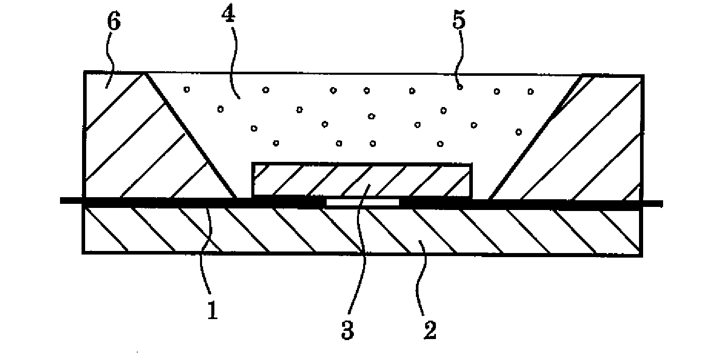
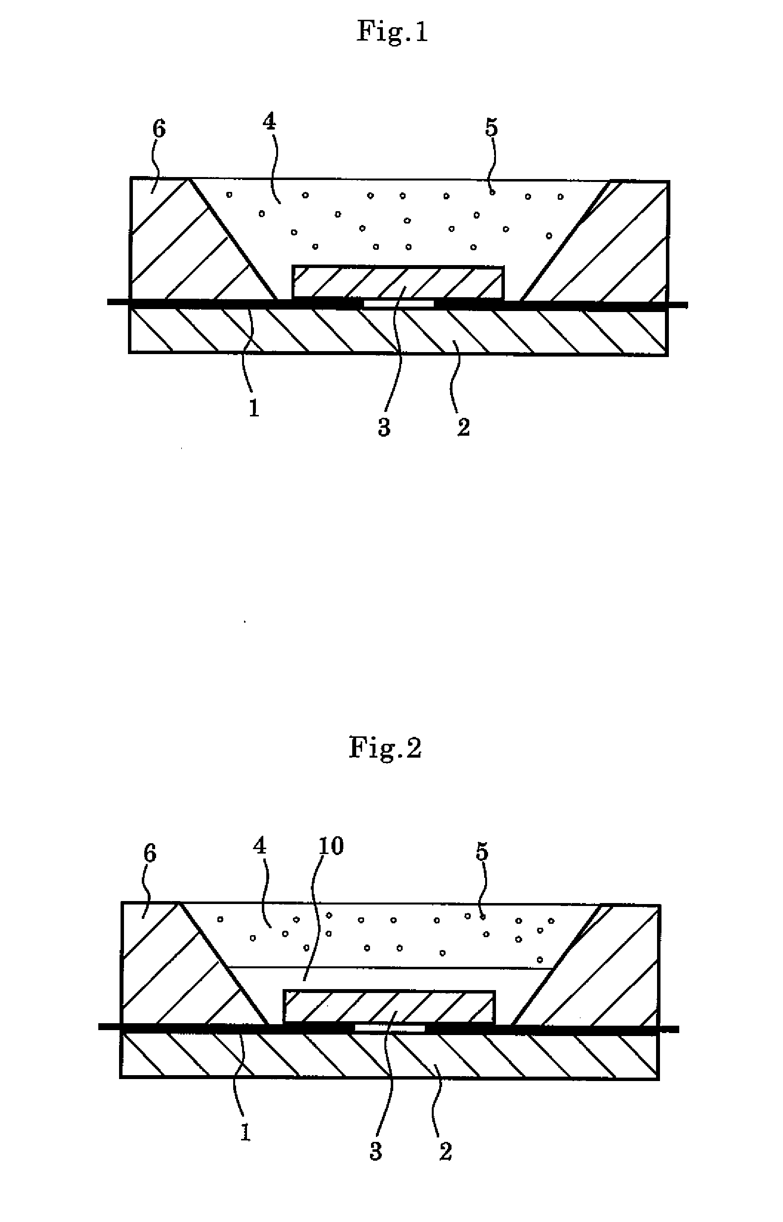
[0020] This requires no raw material having high damaging potential, so that a highly safe wavelength converter can be achieved with a highly safe semiconductor material. Because of high stability of the univalent metal element, the impurity level between bands can be lowered to achieve extremely high quantum efficiency. As the result, the wavelength converter having a conversion efficiency of equal to or more than that of a converter containing CdSe can be provided without using CdSe.
[0029] According to the present invention, there is provided a lighting system assembly having a plurality of the lighting systems. Thus, the lighting system assembly exhibiting high safety, color rendering property, and luminous efficiency can be achieved. This realizes the lighting system assembly being extremely bright and power saving, which may substitute for conventional fluorescent lamps.

Problems solved by technology

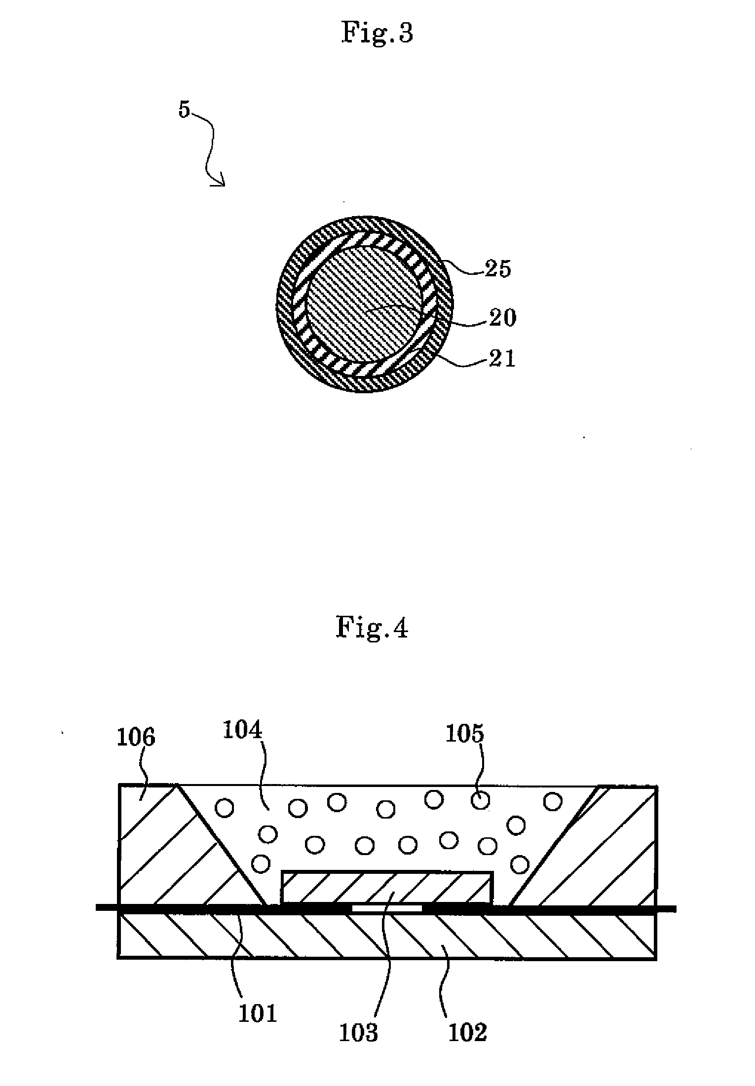
However, when the brightness of the light emitting diode 103 is changed, the ratio of quantity of light of blue to yellow is changed and hence the tone of white is changed, resulting in poor color rendering property.
Nevertheless, in the light emitting unit as described in the publication No. 2002-314142, the luminous efficiency of red component fluorescent substance (for example, Y2O3S: Eu, or the like) with respect to an ultraviolet region in the vicinity of 400 nm of excited light is considerably lower than the other fluorescent substances, failing to achieve white light offering a good luminous balance of red, green, and blue.
Hence, the amounts of emission of the green and blue fluorescent substances become lessened, failing to improve the luminous efficiency of the white light emitting unit.
Although the luminous efficiency can also be improved by increasing the amount of blending of the green and blue fluorescent substances having high luminous efficiency, it is impossible to obtain white light offering a good luminous balance of red, green, and blue.
Although CdSe has a band gap of about 2 eV and can change the particle diameter to change the fluorescent wavelength, it has a strong toxicity that may raise questions of industry and environment.
However, this poses a problem that the fluorescent substance formed of such a composition cannot achieve such a luminous efficiency as high as CdSe.

Method used


Image

  • Wavelength Converter, Lighting System, and Lighting System Assembly
  • Wavelength Converter, Lighting System, and Lighting System Assembly
  • Wavelength Converter, Lighting System, and Lighting System Assembly

Examples


example 1

[0068] Semiconductor ultrafine particles as shown in Table 1 were manufactured with hot soap method in the following manner. First, a predetermined amount of silver chloride (manufactured by KANTO CHEMICAL CO. INC.) and a predetermined amount of indium chloride (manufactured by KANTO CHEMICAL CO. INC.) are separately dissolved in oleyl amine. The respective solutions were then mixed to prepare a solution 1. Next, 7.6 g (0.1 M) of diethyldithio zinc carbamate (manufactured by KANTO CHEMICAL CO. INC.) was dissolved in a mixed solution of oleyl amine and trioctyl phosphine to prepare a solution 2. Adjustments to the solution 1 and the solution 2 were made in an atmosphere of nitrogen. The silver chloride and the indium chloride were added so as to be the ratio of blending (the mole ratio) as shown in Table 1.

[0069] The solution 1 and the solution 2 thus prepared in the above manner were mixed and allowed for reaction with stirring under conditions of the reaction temperature and the r...

examples 2 to 12

[0080] A core shell structure was formed by coating the surfaces of the above-mentioned semiconductor ultrafine particles of Example 1 with a semiconductor material [zinc sulfide (ZnS)] in the following manner. First, the semiconductor ultrafine particles obtained in the above-mentioned manner were added to a mixed solution of 1.1 g of zinc acetate, 9.9 mL of oleic acid, and 300 mL of octadecene, and stirred while heating at 170 degrees Celsius under argon flow for two hours. To this solution, 12 g of sulfur and 1.5 g of trioctylphosphine (TOP) were added and stirred at 300 degrees Celsius. At the completion of the reaction, this was cooled to room temperature. After 200 g of toluene was added thereto and mixed uniformly, ethanol was added and subjected to acceleration of 1500 G for 10 minutes by the centrifugal so as to precipitate the semiconductor ultrafine particles having the core shell structure, the surfaces of which were coated with zinc sulfide.

[0081] To 1 g of each of the...


PUM


Abstract

In a wavelength converter converting a wavelength of light emitted from a light source and outputting an output light containing light whose wavelength is converted, which comprises a fluorescent substance dispersed in a transparent matrix, the fluorescent substance has semiconductor fine particles containing at least one univalent metal element selected from alkali metal and Ag, an element of group III in the periodic table selected from indium and gallium, and sulfur, and does not substantially contain Cd and Se. Hence, a wavelength converter having a conversion efficiency of equal to or more than that of a converter containing CdSe can be provided by using a semiconductor material formed of a highly safe composition.

Description

[0001] Priority is claimed to Japanese Patent Application No. 2005-316809 filed on Oct. 31, 2005, the disclosure of which is incorporated by reference in its entirety. BACKGROUND OF THE INVENTION [0002] 1. Field of the Invention [0003] The present invention relates to a wavelength converter with a fluorescent substance having semiconductor fine particles dispersed in a matrix, a lighting system in which the light emitted from a light emitting diode is subjected to wavelength conversion in a wavelength converter and taken out to the exterior, and a lighting system assembly provided with a plurality of the lighting systems. In particular, the present invention relates to a wavelength converter for lighting, and a lighting system which are suitably used in a backlight power source for an electronic display, or a fluorescent lamp, and the like. [0004] 2. Description of Related Art [0005] A light emitting diode formed of a semiconductor material (hereinafter referred to as an “LED chip” ...

Claims


Application Information

Patent Timeline
IPC IPC(8): H01L33/00H01L33/50
CPCC09K11/565C09K11/623H01L33/502H01L2924/181H01L2224/16225H01L2924/00012
Inventor FUKUDOME, MASATONAKAKAWAJI, FUJITOISHIDA, MASANOBUIRYOU, TSUTAE
Owner KYOCERA CORP
Learn More