
Thin film for package of alkaline battery and thin air battery using the same

a technology of alkaline batteries and thin film, which is applied in the direction of cell components, cell components, jackets/cases materials, etc., can solve the problems of inability to accommodate the battery in the volume allotted to the battery in a small electronic device, the inability to output small amounts, and the inability to use as the main power source for portable electronic devices or small audio systems. , to achieve the effect of preventing degradation of electrolyte, suppressing the expansion of the battery

Inactive Publication Date: 2007-04-05
PANASONIC CORP
View PDF5 Cites 33 Cited by
  • Summary
  • Abstract
  • Description
  • Claims
  • Application Information

AI Technical Summary

Benefits of technology

[0028] According to the present invention, hydrogen gas generated from the negative electrode during storage due to impurities or the like can be discharged to the outside of the battery, and the expansion of the battery can be suppressed. In addition, the permeation of water vapor into and out of the battery, and the invasion of carbon dioxide can be suppressed, and the degradation of the electrolyte can be prevented. Furthermore, the invasion of oxygen into the battery can be prevented, and the self-discharge of the negative electrode active material can be prevented. Therefore, the elevation of internal resistance during the storage period can be suppressed, and a thin air battery having high long-term reliability can be provided.

Problems solved by technology

However, since the button-shaped air battery has a disadvantage that current able to be outputted is small, it is difficult to use as the main power source for portable electronic devices or small audio systems.
However, there is a problem wherein if the battery size is simply enlarged, the battery cannot be accommodated in the volume allotted to the battery in a small electronic device.

Method used


Image

  • Thin film for package of alkaline battery and thin air battery using the same
  • Thin film for package of alkaline battery and thin air battery using the same

Examples


example 1

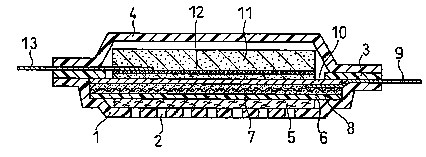
[0048] For sheet layers 1, 3 and 4 of a package, an acid-modified polypropylene (PPa) having a thickness of 0.02 mm was used as a hydrogen gas permeating material, PEN having a thickness of 0.035 mm was used as a gas barrier material, and a sheet constituted to be a three-layer structure of a total thickness of 0.075 mm wherein the both surfaces of the PEN was coated with PPa was used (tab-film (PPa—N), manufactured by Dai Nippon Printing Co. Ltd.).

[0049] The first sheet layer 1 was drawn using a hot press to have a depth of 0.6 mm. In the depression, vinylon fiber paper (thickness: 0.1 mm) as air diffusion paper 5 was placed so as to cover over an air inlet hole 2, and spot bonded with pitch to fix. On the vinylon fiber paper, a fine porous film of polytetrafluoroethylene (PTFE) (thickness: 0.1 mm) as a water repellent film 6, an air electrode 7 (thickness: 0.3 mm), and a fine porous film of polypropylene (PP) (thickness: 0.05 mm) as a separator 10 were sequentially stacked. Over ...

examples 2 to 14

[0056] Hydrogen gas permeating materials, gas barrier materials, and metal materials, the thicknesses thereof, and the compositions and thicknesses of packages composed of these materials are shown in Table 1. The hydrogen gas permeating materials and the gas barrier materials were adhered together by evenly roll-coating modified polybutadiene as an anchor coating agent with a substantially negligible thickness on the surface of the gas barrier material sheets, and bonding the hydrogen gas permeating material sheets thereto. Except using these, thin air batteries were fabricated in the same configurations as in Example 1.

TABLE 1Hydrogen gas permeatingGas barrier materialMetal materialComposition andmaterial and thicknessand thicknessand thicknessthickness ofthereof (mm)thereof (mm)thereof (mm)package (mm)Example 1PPa 0.02PEN 0.035—PPa / PEN / PPa 0.075Example 2PPa 0.02PET 0.035—PPa / PET / PPa 0.075Example 3PPa 0.02PPS 0.035—PPa / PPS / PPa 0.075Example 4PE 0.02PEN 0.035—PE / PEN / PE 0.075Exampl...

examples 15 to 18

[0057] Acid-modified polypropylene (PPa) having a thickness of 0.02 mm was used as hydrogen gas permeating materials, fluorine-containing polymer materials were used as gas barrier materials, and the combinations of the configuration and thicknesses thereof are shown in Table 1. The hydrogen gas permeating materials were adhered to the fluorine-containing polymer materials by surface-modifying the surfaces of the fluorine-containing polymer material sheets by corona discharge, roll-coating modified polybutadiene, which was an anchor coating agent, on the surface of the fluorine-containing polymer material sheets, and bonding the hydrogen gas permeating material sheets on the coating surface. Except using these, thin air batteries were fabricated in the same configurations as in Example 1.


PUM


Abstract

There is provided a thin air battery comprising a power-generating element including air diffusion paper and a water repellent film, the power-generating element sealed in a package composed of first and third sheet layers that cover the air electrode side and negative electrode side of the power-generating element, and a second sheet layer disposed in the peripheral portion between the two sheet layers and joined to the two sheet layers. The sheet layers are each composed of a thin film formed by stacking an alkali resistant polymer film having hydrogen gas permeability and a polymer film having gas barrier properties, and in each of the first and third sheet layers, the polymer film having hydrogen gas permeability is disposed on the internal surface side. According to the present invention, a thin air battery that has high energy density and has excellent long-term reliability is provided.

Description

TECHNICAL FIELD [0001] The present invention relates to thin air batteries that have very high energy density and have excellent long-term reliability. The present invention also relates to a thin film for a package used in an alkaline battery, such as an air battery. BACKGROUND ART [0002] Since an zinc air battery used an air electrode using oxygen in the air as a positive electrode active material, it has been applied to various devices for aids to navigation, various communications, and telephones, as an economical power source that can be used for a long period without maintenance. Among these, since a button-shaped zinc air battery has features such as high energy density, lightweight and economical, compared with other batteries having similar shapes, the range of application thereof have been expanding, and the present major application thereof is a power source for hearing aids. [0003] However, since the button-shaped air battery has a disadvantage that current able to be ou...

Claims


Application Information

Patent Timeline
IPC IPC(8): H01M2/12H01M12/06H01M4/86H01M50/121H01M50/145
CPCH01M2/0222H01M2/0255H01M2/0265H01M2/0287H01M4/8605H01M12/06Y02E60/50Y02E60/10H01M50/109H01M50/1385H01M50/124H01M50/121H01M50/145
Inventor TAKAMURA, KOSHISHIMAMURA, HARUNARIKOSHIBA, NOBUHARU
Owner PANASONIC CORP
Learn More